Powering the Modular Switch
The switch operates with multiple power supplies. The following table lists the quantity of modules each chassis can contain and the minimum operating requirements for each model.
Installation of this equipment must comply with local and national electrical codes. If necessary, consult with the appropriate regulatory agencies and inspection authorities to ensure compliance.
Installation de cet équipement doit être conformes aux codes électriques locaux et nationaux. Si nécessaire, consulter les organismes de réglementation appropriés et des autorités de contrôle pour assurer la conformité.
| Switch Model | Chassis Capacity
(Power Supply Units) |
Minimum Operating Requirements
(non-redundant power) |
|---|---|---|
| DCS-7388X5 | 4 | 1 active circuit |
Each power supply requires input branch circuit protection in compliance with AHJ requirements.
Chaque alimentation nécessite une protection du circuit de la branche d’entrée conformément aux exigences de l’AHJ.
The power supplies are located on the Rear Panels of the switch. Unpopulated power supply bays must be covered using the appropriate “blank” for the switch.
This chapter includes sections that describe procedure for grounding and cabling power supplies. After completing the instructions for your switch, proceed to Connecting Serial and Management Cables.
Read all installation instructions before connecting the system to the power source.
Lire toutes les instructions d'installation avant de brancher le système à la source d'alimentation.
- Non-Redundant Configuration: Provide power to the minimum required power inputs.
- Redundant Power Supply Configuration: Connecting power to modules in excess of minimum requirements protects the switch against failed modules and can provide grid-level redundancy.
- Power down the Switch: Remove all power cords from the power input sockets.
This equipment must be grounded. Never defeat the ground conductor. This unit requires over-current protection.
Cet équipement doit être mis à la terre. Ne jamais modifier le conducteur de terre. Cet appareil nécessite de protection contre les surintensités.
Cabling the AC Power Supply
Grounding the Switch
After mounting the switch into the rack, connect the switch to the data center ground. The following figure displays the location of the grounding pads located on the rear of the switch.
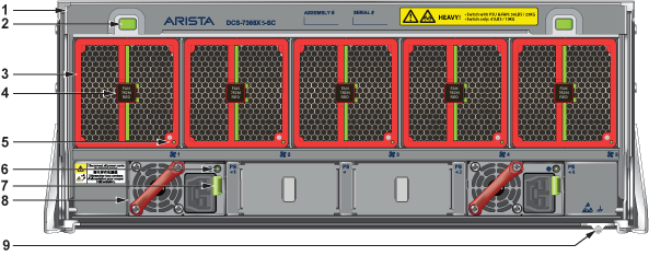
| 1 | Switch Card Module Release Handle | 4 | Fan Module Release | 7 | PSU Release |
| 2 | Switch Card Module Release Buttons | 5 | Fan Status LED | 8 | PSU |
| 3 | Fan | 6 | PSU Status LED | 9 | Ground |
Grounding wires and grounding lugs (M4 x 0.7) are not supplied. Wire size should meet local and national installation requirements. Commercially available 6 AWG wire is recommended for installations in the U.S.
À la terre et de mise à la terre fils cosses (M4 x 0.7) ne sont pas fournis. Calibre des fils doit satisfaire des exigences de l’installation locale et nationale. Disponible dans le commerce des câbles 6 AWG sont recommandé pour les installations aux États-Unis.
After the switch is grounded, ESD wrist straps can be grounded by connecting them to the ESD port on the front of the switch.
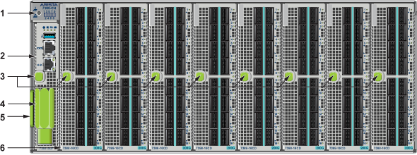
| 1 | ESD attach point | 3 | Supervisor and Linecard Ejector Handle (Release) and Button | 5 | Pull Tag (for Switch Information) |
| 2 | Supervisor Module | 4 | Torque Clutch Removal Tool | 6 | Linecard |
Connecting Power Cables to an AC Power Supply
The following figure displays an AC power supply module, including the power input socket.
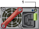
| 1 | Power Supply Status LED |
The power supplies require a SAF-D cable for connection.
To insert a power cable:
DC Power Supplies
The following DC power supplies are supported.
- PWR-2411-DC-RED
- PWR-2421-HV
The following image displays the DC power supply.
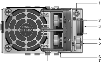
| 1 | Power Supply Status LED | 4 | RTN (Battery return) Terminal | 7 | Plastic Cover |
| 2 | -48V Terminal | 5 | Protective Earth Terminal | ||
| 3 | Release | 6 | Plastic Cover Handle |
A disconnect device must be provided as part of the installation.
Un dispositif de sectionnement doit être fourni dans le cadre de l'installation.
Ensure power is removed from DC circuits before performing any installation actions. Locate the disconnect device, circuit breakers or fuses on DC power lines servicing the circuits. Turn off the power line circuits or remove the fuses.
Pouvoir assurer qu'il est retiré de circuits DC avant d'effectuer des actions d'installation . Localiser les disjoncteurs ou des fusibles sur les lignes de courant continu desservant les circuits. Coupez les circuits de lignes d'alimentation ou retirer les fusibles.
Wire size must comply with local and national requirements and electrical codes. Use only copper wire.
Le calibre du fil doit être conforme aux exigences locales et nationales et les codes électriques. Utiliser du fil de cuivre.
Apply ground connection to the switch first during installation and remove last when removing power.
Appliquer connexion à la terre à l'interrupteur premier lors de l'installation et de supprimer la dernière alimentation lors du débranchement.
Wire and Lug Preparation
Before performing any installation actions, ensure power is removed from DC circuits by turning off the power line servicing the circuits. Prepare the stranded wiring before you begin a DC power installation.
- Attach an ESD grounding strap.
- Prepare the stranded copper wiring for the power supply to be used. The following table provides wiring, lug, and tightening torque information for the power supplies covered in this guide.
Table 2. Wiring, Lug, and Tightening Torques for DC PSUs PSU Wire Size(1) Lug Type(2) Tightening Torque (AWG) (mm2) N•m in.•lbs. PWR-2411-DC 2 - 4 35.0 - 25.0 2.7 24 1 Unless otherwise noted, wire size applies to -48V, Battery return, and Protective earth wires.
2 Unless otherwise noted, twin #10 studs spaced for dual-hole lug with 5/8" hole spacing.
- Strip the wires to the appropriate length for the lugs to be used.
- Slip on heat-shrink tubing on the wire ends before assembling the lugs on to the wire.
- Crimp the lugs with the proper tool, and ensure that the tubing extends over the barrel of the lugs and the insulation on the wires.
- Use agency-approved compression (pressure) lugs for wiring terminations.
- Shrink the tubing with a heat gun.
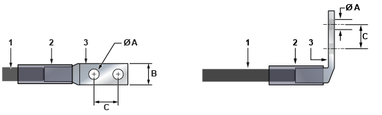
| 1 | Insulated wire | 2 | Heat-shrink tubing | 3 | Lug |
| A | 1/4” | B | 1/2” | C | 5/8” |
Connecting a DC Power Supply to Power Source
To connect a DC power supply to a power source, perform the following:
- Prepare the stranded wiring (Wire and Lug Preparation).
- Attach the appropriate lugs to the source DC wires.
- Connect the DC-input wires to the appropriate terminals using the specified torque in the following order.
Note: Remove terminal covers as needed.
- Ground wire to the Protective Earth (PE) terminal.
- Negative source DC cable to the negative (-48V) terminal.
- Positive (+) source DC cable to the positive (RTN) terminal.
- Replace the terminal covers as required.
Note: The ground (protective earth) terminal is on the opposite side from the other two terminals.