Preparation
Site Selection
Consider the following criteria when selecting a site to install the switch:
Floor Space:Install the switch in an area that provides adequate clearance for removing front and rear components. The following figure displays switch clearance requirements.
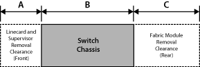
The following table shows the clearance dimensions for the modular switches.
| Switch | Clearance Requirements Dimensions | ||
|---|---|---|---|
| A | B | C | |
| DCS-7358X4 | 25.4 cm
(10 inches) |
64.0 cm
(25.2 inches) |
55.9 cm
(22.0 inches) |
| DCS-7368X4 | 25.4 cm
(10 inches) |
64.0 cm
(25.2 inches) |
55.9 cm
(22.0 inches) |
| DCS-7289R3A | 25.4 cm
(10 inches) |
76.7 cm
(30.2 inches) |
66.0 cm
(26.0 inches) |
- Temperature and Ventilation: For proper ventilation, install the switch with ample airflow to the front and back of the switch. The temperature should not go below 0° or exceed 40°C.
When applying labels to any switch, avoid covering ventilation perforations in the front and rear panels. Apply labels only to solid surface areas where there are no perforations. Use the pull-out tag on the front or rear of the switches, when provided, to apply custom labels. For switches that include a plastic tag with the accessory kit, use a single ventilation hole to clip the tag.
Important:To prevent the switch from overheating, do not operate it in an area where the ambient temperature exceeds 40°C (104°F).
Pour empêcher l'interrupteur de surchauffe, ne pas utiliser il dans une zone où la température ambiante est supérieure à 40°C (104°F). - Airflow Orientation: Determine the airflow direction of the fan modules and power supply modules. Fan and power supply module handles indicate airflow direction.
Note: Your switch configuration may not support all power supplies.
The Rear Panels display power supply and fan module locations on the rear panel. Verify the airflow direction of all modules (all rear panel modules have the same color handles).
Orient the switch to ensure the air intake modules face the cool aisle. Contact your sales representative if the airflow direction is incompatible with the installation site.
- Rack Space: Install the switch in a 19" rack or cabinet. The switch height depends on the switch model, as specified in Table 1. Verify that the removal clearances (Table 1) provide adequate space for the power and data cables that connect to the switch.
When mounting the switch in a partially filled rack, load the rack from bottom to top, with the heaviest equipment at the bottom. Load the switch at the bottom if it is the only item in the rack.
The accessory kit provides mounting brackets for four-post racks. Two-post mounting racks are not supported.
- Power Requirements: Power requirements vary by switch. Refer to Table 2, and Table 3 for information regarding your specific system.
Multiple circuits provide redundancy protection. The switch uses power cables that have an IEC-320 C19 plug. The accessory kit provides IEC-320 C19 to C20 power cables.
Important:All power input plug-socket combinations must be accessible at all times; they provide the primary method of disconnecting power from the system.
Toutes les combinaisons de fiche-prise d’entrée de puissance doivent être accessibles en tout temps; ils fournissent le principal moyen de coupure d’alimentation du système. - Other Requirements: Select a site where liquids or objects cannot fall onto the equipment and foreign objects are not drawn into the ventilation holes. Verify these guidelines are met:
- Clearance areas to the front and rear panels allow for unrestricted cabling.
- All front and rear panel indicators can be easily read.
- AC power cords can reach from the AC power outlet to the connectors on the rear panel.
Important:
Disconnecting power to all input sockets is required to turn off the unit completely.
La déconnexion de l'alimentation de toutes les prises d'entrée est nécessaire pour éteindre complètement l'appareil.
Tools Required for Installation
Each switch provides an accessory kit that contains parts for installing the switch into a four-post rack. Two-post rack mount parts are available through your sales representative. Accessory kits do not include screws, nuts, or bolts for attaching the switch to a conventional rack.
In addition to the accessory kit, the following tools are required to install a modular switch:
All Racks
A mechanical device capable of lifting an installed chassis (the chassis weight is listed in the Table 1).
Four-Post Tool-less Rack
No additional equipment is required.
Four-Post Conventional Rack
- Screws or rack mounting nuts and bolts.
- Screwdriver.
Electrostatic Discharge (ESD) Precautions
- Assemble or disassemble equipment only in a static-free work area.
- Select a conductive work surface (such as an antistatic mat) to dissipate static charge.
- Wear an ESD wrist strap to dissipate static charge accumulation.
- Minimize handling of assemblies and components.
- Keep replacement parts in their original static-free packaging.
- Remove all plastic, foam, vinyl, paper, and other static-generating materials from the work area.
- Select tools that do not create ESD.