Maintenance and Field Replacement
Switchcard Module
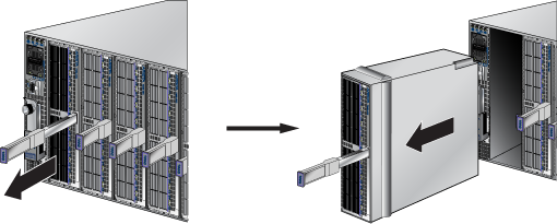
The switchcard module is accessible from the rear of the switch, as shown in Rear Panels. Refer to the following figure for more details on removing and replacing the switchcard module.
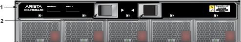
| 1 | Switchcard Release Handle | 2 | Switchcard Release Lever |
The module includes lock levers that secure it to the chassis. The module and the lock levers are easily damaged by improperly removing, inserting, or handling. Use caution while lifting or moving the module after removing it from the chassis.
Removing the Switchcard Module
- Ground yourself with an ESD wrist strap.
- Move the release handle down.
- Pinch the release levers towards the center to unlock the module from the chassis.
- Carefully remove the switchcard module from the chassis while supporting it.
Inserting the Switchcard Module
Power Supplies
The power supplies are accessible from the rear of the switch, as shown in Rear Panels. Refer to Removing a Power Supply for more details on removing and replacing a power supply unit.
The following steps are required when removing power supplies from a switch.
Removing a Power Supply
- Push the power supply release handle and remove the power supply, as shown in the following figure.
Figure 2. Power Supply Removal
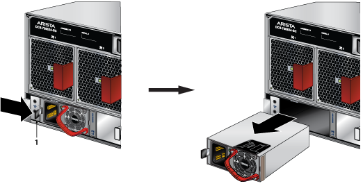
1 PSU Release Handle
Installing a Power Supply
Fan Modules
The fan modules are accessible from the rear of the switch, as shown in Rear Panels.
Removing a Fan Module
- Push the fan module release lever and slide the fan module out of the switch, as shown in the following figure.
Figure 3. Fan Module Removal
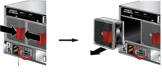
1 Fan Module Release Lever
Installing a Fan Module
Supervisor Module
The supervisor module is accessible from the front of the switch, as shown in Front Panels. Refer to the following figure for more details on removing and replacing a supervisor module.
Removing a Supervisor Module
- Put on a grounded ESD strap.
- Lift the supervisor module ejector latch and move the latch down to release the supervisor module.
- Gently remove the supervisor module by pulling it outwards.
Installing a Supervisor Module
- Put on a grounded, anti-static ESD strap.
- Unpack the supervisor module to be installed.
- Slide the supervisor module into the slot.
- Raise the ejector handle and latch it into place.
- Verify that the module is operating normally.
Linecards
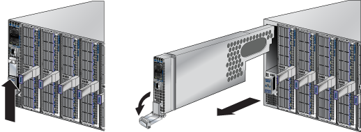
The linecards are accessible from the front of the switch, as shown on Front Panels. The linecards are hot-swappable. It would help to consider that the linecard you are inserting is compatible with the switch and the linecard you are replacing. Refer to the following figure for more details on removing and replacing a linecard module.
Removing a Linecard
- Put on a grounded, anti-static ESD strap.
- Use the ejector handle or lever in the middle of the linecard to release it from the chassis.
- Slide the linecard gently out of the slot.
Installing a Linecard
- Put on a grounded, anti-static ESD strap.
- Unpack the linecard to be installed.
- Slide the linecard gently into the slot.
- Use the ejector handle of the linecard to seat the linecard into the chassis.
- Verify that the linecard is operating normally (Table 2).
Optical Transceivers
For more information about supported optical transceivers and how to remove or install them, refer to https://www.arista.com/assets/data/pdf/Transceiver-Guide.pdf.