Access Point Overview
O-435E is a multi-radio 802.11be (Wi-Fi 7) access point. Refer to the datasheet for more information.
Front Panel
The front panel of the AP has 6 LEDs indicating the status of AP functions.
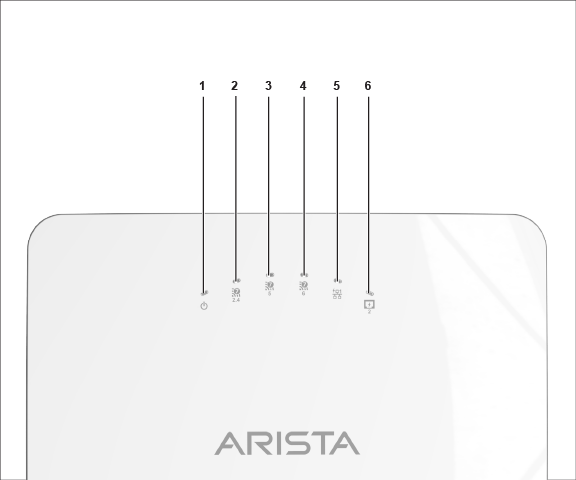
| Label | Description |
|---|---|
| 1 | Power |
| 2 | 2.4 GHz Radio |
| 3 | 5 GHz Radio |
| 4 | 6 GHz Radio |
| 5 | LAN1 PoE PD |
| 6 | LAN2 PoE PSE (802.3af) |
Power LED
The following table describes the Power LED states:
| Green | Red | |
|---|---|---|
| Solid | Running at full capability | Running at reduced capability. |
| Blinking | Received an IP address, but not connected to the server. | Did not receive an IP address. |
Reduced capability indicates that the AP receives lower than the required maximum power from the PoE++ switch. It means the AP receives 802.3at instead of 802.3bt.
LAN1 LED -ON when the corresponding interface up.
LAN2 LED - ON when the corresponding interface up, and either wired guest or link aggregation configured.
Radio LEDs: ON when the corresponding radio operational.
Side Panel - Left
The side panel of the AP has a reset pinhole and console port.
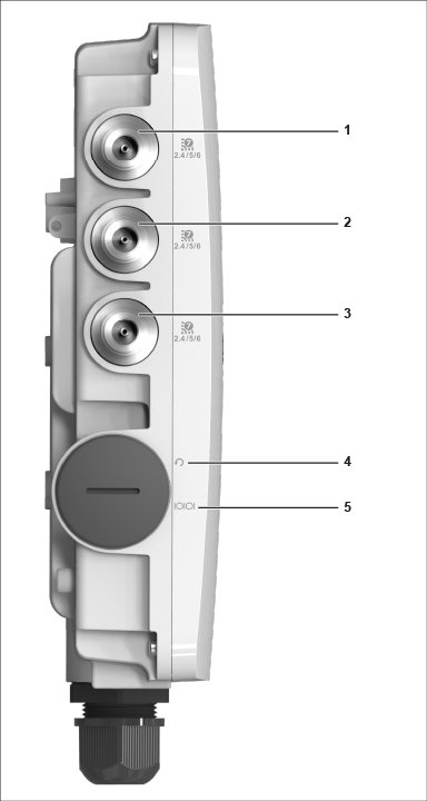
| Label | Description |
|---|---|
| 1, 2, 3 | Antenna Port for 2.4/5/6 GHz. The AP has three (3) antenna ports on the left and right side of the AP. |
| 3 | Reset pin |
| 4 | Console |
| Port | Description | Connector Type | Speed/Protocol |
|---|---|---|---|
| Console |
Establish a ‘config shell’ terminal session through a serial connection. |
RJ-45 |
|
| Reset |
Reset to factory default settings port. Hold down and power cycle the device to reset. |
Pinhole push button | N/A |
When you reset the AP, the following settings also change:
- The Config shell password resets to config.
- Server discovery value erases and changes to the default, redirector.online.spectraguard.net (primary) and wifi-security-server (secondary).
- The AP loses all the VLAN configurations.
- If the AP has a static IP configured, the reset erases the IP address and the AP sets to DHCP mode with the factory default IP address of 169.254.11.74.
Bottom Panel
The bottom panel of the AP has two ports, LAN1 and LAN2. Connect a wired LAN from a switch or a hub to the LAN1/PoE++ port of the AP to power on the AP. The LAN1 port supports the 802.3bt power standard. Use an active wrench to open the LAN cap. The LAN cap has a width of27 mm. LAN2 acts as a PoE Power Sourcing Equipment (PSE) that provides power to any devices connected through LAN2. You cannot use LAN2 to provide power to the AP.
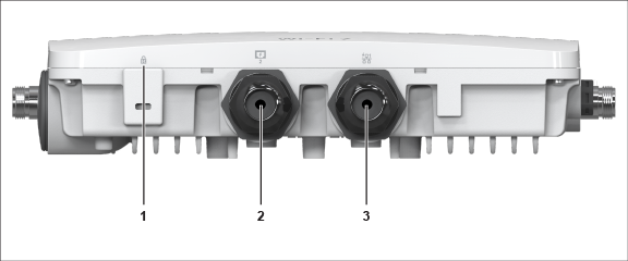
| Label | Description |
|---|---|
| 1 | Kensington lock |
| 2 | LAN2 (PoE PSE) |
| 3 | LAN1 (PoE+ PD) |
| Port | Description | Connector Type | Speed/Protocol |
|---|---|---|---|
| LAN 1 | 5Gbps Ethernet with 802.3bt compliant PoE PD. | RJ-45 | 10M/100M/1000Mbps/2.5G/5Gbps Ethernet |
| LAN 2 | 5Gbps Ethernet with 802.3af compliant PoE PSE. | RJ-45 | 10M/100M/1000Mbps/2.5G/5Gbps Ethernet |