Line Cards
This appendix displays the line cards supported by modular switches covered by this guide.
DCS-7548S-LC 
DCS-7500E-36Q-LC 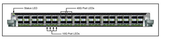
DCS-7500E-72S-LC 
DCS-7500E-48S-LC 
DCS-7500E-12CM-LC 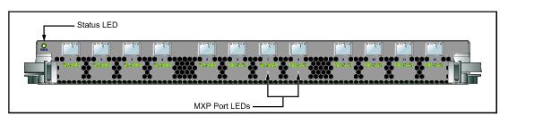
DCS-7500E-6C2-LC 
DCS-7500E-12CQ-LC 
DCS-7500E-6CFPX-LC 
Rear Panel
This appendix displays the rear panel of all switches covered by this guide.
DCS-7508 Rear Panel 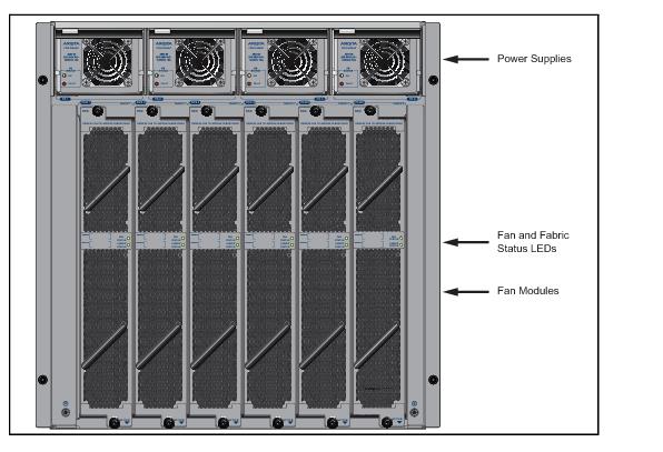
DCS-7504 Rear Panel 
DCS-7508E Rear Panel 
DCS-7504E Rear Panel 
Front Panel
This appendix displays the front panel of all switches covered by this guide.
DCS-7508 Front Panel (fully populated) 
DCS-7504 Front Panel (fully populated) 
DCS-7508E Front Panel (fully populated) 
DCS-7504E Front Panel (fully populated) 
Parts List
Each switch provides an accessory kit that contains parts that are required to install the switch. This appendix lists the installation parts contained in the switch accessory kit.
Two-Post Rack Mount Parts
|
Quantity
|
Description
|
|
2
|
Center-mount brackets.
|
|
20
|
M4x8 panhead Phillips screws.
|
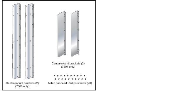
Figure B-1: Two-Post Rack Mount Parts
Four-Post Rack Mount Parts
|
Quantity
|
Description
|
|
2
|
Front brackets.
|
|
4
|
Shelf supports.
|
|
2
|
Back brackets.
|
|
1
|
Left shelf.
|
|
1
|
Right shelf.
|
|
10
|
M6X16 panhead Phillips screws.
|
|
4
|
M6 Cage Hex Nuts.
|
|
2
|
M6 Cage Nut Square Hole Racks.
|
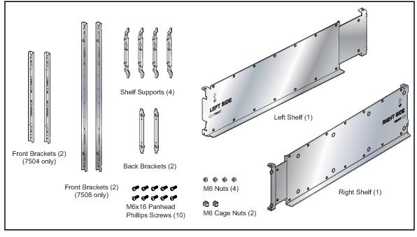
Figure B-2: Four-Post Rack Mount Parts
Parts Used in All Rack Mount Configurations
Cables
|
Quantity
|
Description
|
|
4
|
power cables: 14 AWG, C19-C20, 2 meters.
|
|
2
|
RJ-45 Patch Panel Cables, 2 meters.
|
|
2
|
RJ-45 to DB9 Adapter Cable, 2 meters.
|
Warning All provided power cables are for use only with Arista products.

Equipment
|
Quantity
|
Description
|
|
1
|
Adjustable Wrench.
|
Rack Mount Alternate Parts
These parts are supplied for threaded racks that do not use M6 screws.
|
Quantity
|
Description
|
|
5
|
M5 hex nuts.
|
|
11
|
M5X16 panhead Phillips screws.
|
|
5
|
12-24 hex nuts.
|
|
11
|
12-24X5/8 panhead Phillips screws.
|
|
5
|
10-32 hex nuts.
|
|
11
|
10-32X5/8 panhead Phillips screws.
|
|
3
|
M6 cage nuts.
|
Status Indicators
Supervisor Module
While the front panel of each switch can house two supervisors, switch operations require only one. Supervisors display switch component status and contain Ethernet management and console ports. Appendix C displays the supervisor location on each switch.
The supervisor style depends on the switch model. These sections describe both supervisor styles.
Supervisor Indicators: 7508/7504
The 7508/7504 supervisor provides a serial console port, an Ethernet management port, and a USB port. Supervisor activity is reported by LEDs in the upper left quadrant. The Status Summary Screen in the center reports status for other components. Figure A-1 depicts the 7508/7504 Supervisor Module.

Figure A-1: Supervisor Module: 7508 / 7504
Supervisor Activity Status
The Status and Active LEDs report supervisor activity status. Table A-1 interprets the states of both LEDs.
|
LED Name
|
LED State
|
Supervisor State
|
|
Status LED
|
Off
|
Module failed or is improperly inserted.
|
|
Status LED
|
Green
|
Supervisor operating normally.
|
|
Status LED
|
Red
|
Module failed.
|
|
Active LED
|
Off
|
Supervisor is not active.
|
|
Active LED
|
Green
|
Supervisor is active and controlling the switch.
|
Component Activity Status
The Supervisor Status Summary Screen displays indicators for the power supplies, fabric module, fan modules and line cards. Table A-2 interprets the states of the indicators that the screen displays.
|
LED State
|
Status
|
|
Gray
|
Module not present or improperly inserted.
|
|
Green
|
Module operating normally.
|
|
Red
|
Module has failed.
|
Supervisor Indicators: 7508E / 7504E
The 7508E/7504E supervisor provides one serial console port, two Ethernet management ports, two USB ports, and one clock input port. Supervisor activity is reported by LEDs in the upper left corner. Four LEDs located left of the input ports report status of other switch components. Figure A-2 displays the 7508E/7504E Supervisor Module.
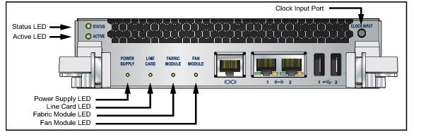
Figure A-2: Supervisor Module: 7508E / 7504E
Supervisor Activity Status LEDs
The Status and Active LEDs are located on the left side of the Supervisor Module. Table A-3 interprets the states of these two LEDs.
|
LED Name
|
LED State
|
Supervisor State
|
|
Status
|
Off
|
Module failed or is improperly inserted.
|
|
Green
|
Supervisor operating normally.
|
|
|
Red
|
Module failed.
|
|
|
Active
|
Off
|
Supervisor is not active.
|
|
Green
|
Supervisor is active and controlling the switch.
|
Component Activity Status LEDs
LEDs located below the vents and left of the input ports display summary indicators for power supplies, fabric modules, fan modules, and line cards. Table A-4 interprets the states of these indicators. When error conditions are indicated, refer to LEDs on the specified modules to determine the condition’s source.
|
LED Name
|
LED State
|
Module State
|
|
Power Supply,
Line Card Fabric Module |
Off
|
No modules are present or powered.
|
|
Green
|
All powered modules are operating normally.
|
|
|
Red
|
At least one module has failed.
|
|
|
Fan Modules
|
Amber
|
At least one fan is missing or has failed.
|
|
Green
|
All modules are operating normally.
|
|
|
Red
|
There are insufficient functional fans installed in the switch.
|
Line Card Module Indicators
Each line card module provides one status LED plus LEDs for each port on the card. The figures in Appendix E indicate the location of the LEDs on each line card. Figure A-3-left displays the status LED and Port LEDs on the left side of the DC-7548S-LC line card. Figure A-3-right displays the status LED and Port LEDs on the left side of the DCS-7500E-36Q-LC line card.

Figure A-3: line card Status LED
The line card Status LED is in the top left corner of the DC-7548S-LC line card. Table A-5 interprets the states of the Status LED.
|
LED State
|
Status
|
|
Off
|
line card not inserted.
|
|
Green
|
line card operating normally.
|
|
Yellow
|
line card administratively shut down.
|
|
Red
|
Module has failed.
|
The line card provides LEDs for each port module socket:
• Figure A-3-left displays SFP module LEDs. Each LED corresponds to a module.
• Figure A-3-right displays QSFP module LEDs. A set of four LEDs correspond to each module. When the module is programmed as a 40G port, the first LED in the set reports status. When the module is programmed as four 10G ports, each port is assigned to an LED within the set.
Table A-6 interprets the port LED states.
|
LED State
|
Status
|
|
Off
|
Port link is down.
|
|
Green
|
Port link is up.
|
|
Yellow
|
Port is disabled in software.
|
Fan and Fabric Status Indicators
Fan and Fabric Status LEDs are on fan modules (DCS-7508) or fan-fabric modules (DCS-7504, DCS-7508E, and DCS-7504E). Appendix D displays the position of these LEDs on the rear of each switch. Figure A-4 displays Fan Status and Fabric Status LEDs on the DCS-7508 and DCS-7504 switches.

Figure A-4: Fan Status and Fabric Status LEDs
Table A-7 interprets the states of the Fan and Fabric Status LED.
|
LED State
|
Status
|
|
Off
|
Module inserted, but status is unknown.
|
|
Green
|
Module operating normally
|
|
Red
|
Module failed
|
Configuring the Switch
Arista switches ship from the factory in Zero Touch Provisioning (ZTP) mode. ZTP configures the switch without user intervention by downloading a startup configuration file or a boot script from a location specified by a DHCP server. To manually configure a switch, ZTP is bypassed. The initial configuration provides one username (admin) accessible only through the console port because it has no password.
When bypassing ZTP, initial switch access requires logging in as admin, with no password, through the console port. Then you can configure an admin password and other password protected usernames.
This manual configuration procedure cancels ZTP mode, logs into the switch, assigns a password to admin, assigns an IP address to the management port, and defines a default route to a network gateway.
Step 1 Provide power to the switch (Section 4.1.2).
Step 2 Connect the console port to a PC (Section 4.2).
As the switch boots without a startup-config file, it displays this message through the console:
The device is in Zero Touch Provisioning mode and is attempting to
download the startup-config from a remote system. The device will not
be fully functional until either a valid startup-config is downloaded
from a remote system or Zero Touch Provisioning is cancelled. To cancel
Zero Touch Provisioning, login as admin and type 'zerotouch cancel'
at the CLI.
localhost login:
Step 3 Log into the switch by typing admin at the login prompt.
localhost login:admin
Step 4 Cancel ZTP mode by typing zerotouch cancel. IMPORTANT: This step initiates a switch reboot.
localhost>zerotouch cancel
Step 5 After the switch boots, log into the switch again by typing admin at the login prompt.
Arista EOS
localhost login:admin
Last login: Fri Mar 15 13:17:13 on console
Step 6 Enter global configuration mode.
localhost>enable
localhost#config
Step 7 Assign a password to the admin username with the username secret command.
localhost(config)#username admin secret pxq123
Step 8 Configure a default route to the network gateway.
localhost(config)#ip route 0.0.0.0/0 192.0.2.1
Step 9 Assign an IP address (192.0.2.8/24 in this example) to an Ethernet management port.
localhost(config)#interface management 1/1
localhost(config-if-Ma1/1)#ip address 192.0.2.8/24
Step 10 Save the configuration by typing write memory or copy running-config startup-config.
localhost#copy running-config startup-config
When the management port IP address is configured, use this command to access the switch from a host, using the address configured in step 9:
ssh admin@192.0.2.8
Refer to the Arista Networks User Manual for complete switch configuration information.
Cabling the Switch
Cabling the AC Power Supply
Grounding the Switch
After mounting the switch into the rack, connect the switch to the data center ground. Figure 4-1 displays the location of the grounding pads located on both sides of the power input sockets.

Figure 4-1: Grounding Pad and ESD Grounding Port Sockets
After the switch is grounded, ESD wrist straps can be grounded by connecting them to one of the ESD grounding ports located between the power input sockets, (Figure 4-1) or the rear panel (Figure 4-2 depicts the location on the 7504). Receptacles are available in similar locations on other switch models.
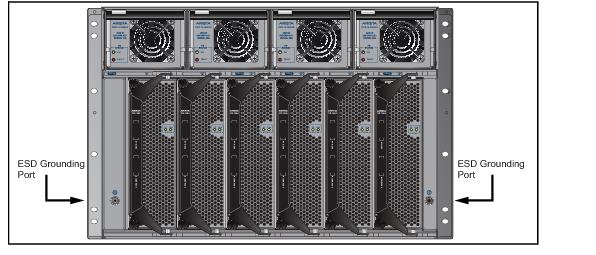
Figure 4-2: ESD Grounding Port – Rear Panel
Connecting Power Cables to an AC Power Supply
Important! Installation of this equipment must comply with local and national electrical codes. If necessary, consult with the appropriate regulatory agencies and inspection authorities to ensure compliance.
Installation de cet équipement doit être conformes aux codes électriques locaux et nationaux. Si nécessaire, consulter les organismes de réglementation appropriés et des autorités de contrôle pour assurer la conformité.
Installation de cet équipement doit être conformes aux codes électriques locaux et nationaux. Si nécessaire, consulter les organismes de réglementation appropriés et des autorités de contrôle pour assurer la conformité.
The switch operates with four power supplies, each of which connects to circuits that provide 200-240 VAC, 50 or 60 Hz, and 20 A.
• DCS-7504 / 7504E requires the connection of one power supply to an active live circuit.
• DCS-7508 / 7508E requires the connection of at least two power supplies to active circuits.
Connecting power to all four power supplies protects against up to two failed power supplies and can provide grid-level redundancy. Energizing any power supply causes all power supply fans to function.
Figure 4-3 displays the power input sockets. Appendix C displays the front panel location of the sockets.

Figure 4-3: Power Input Sockets
Important! Read all installation instructions before connecting the system to the power source.
Lire toutes les instructions d’installation avant de brancher le système à la source d’alimentation.
Lire toutes les instructions d’installation avant de brancher le système à la source d’alimentation.
• Non-Redundant Configuration: Provide power to any two of the four power inputs.
• Redundant Power Supply Configuration: Provide power to all four power inputs.
• Power down the Switch: Remove all power cords from the power input sockets.
Each power supply includes a fan that maintains proper power supply temperature and cools the supervisor modules located below the power input sockets. The power supply fans are in addition to the fan modules located behind the power supplies. These appendices display the location of the following component on all switches described in this guide.
• Appendix C displays the front panel location of the power input sockets and supervisor modules.
• Appendix D displays the rear panel location of power supplies and fan modules.
The switch uses power cables that comply with IEC-320 and have a C19 plug. The accessory kit provides four IEC-320 C19 to C20 power cables, each two meters long.
To insert a power cable:
Step 1 Lift the retaining clip on each power input socket.
Step 2 Plug the power cables into the sockets.
Step 3 Adjust the retaining clips if needed for your power cords.
Step 4 Push the retaining clip back down over the cable.
Important! This equipment must be grounded. Never defeat the ground conductor.
Cet équipement doit être mis à la terre. Ne jamais modifier le conducteur de terre.
Cet équipement doit être mis à la terre. Ne jamais modifier le conducteur de terre.
Important! This unit requires overcurrent protection.
Cet appareil requiert une protection contre les surintensités.
Cet appareil requiert une protection contre les surintensités.
Connecting Supervisor Cables
Supervisor modules contain console, management, and USB ports. Figure 4-4 displays port locations on supervisors provided with 7508 / 7504 switches.

Figure 4-4: Supervisor Ports: 7508 / 7504 Switches
Figure 4-5 displays port locations on supervisors provided with 7508E / 7504E switches.
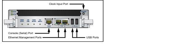
Figure 4-5: Supervisor Ports: 7508E / 7504E Switches
• Console (Serial) Port: Connect to a PC with RJ-45 to DB-9 serial adapter cable. Default switch settings include:
• 9600 baud
• No flow control
• 1 stop bit
• No parity bits
• 8 data bits
• Ethernet management port: Connect to 10/100/1000 management network with RJ-45 cable.
• USB Port: May be used for software or configuration updates.
Connecting Line Card Modules and Cables
Install required SFP, SFP+, and QSFP+ optic modules in line card module ports (Figure 4-6).

Figure 4-6: SFP or SFP+ ports
Connect cables as required to line card module ports or fixed MPO ports. Supervisor and line card module ejectors on the front of the chassis assist with cable management.
Caution Excessive bending can damage interface cables, especially optical cables.
Flexion excessive peut endommager les câbles d’interface, notamment des câbles optiques.
Flexion excessive peut endommager les câbles d’interface, notamment des câbles optiques.
Rack Mounting the Switch
The accessory kit provides components for installing the switch in two-post and four-post racks.
• Section 3.1 provides instructions for mounting the switch in a two-post rack.
• Section 3.2 provides instructions for mounting the switch in a four-post rack.
The rack mounting procedure is identical for all modular switches. Illustrations in this chapter depict the mounting of an unpopulated DCS-7508 chassis.
After completing the instructions for your rack type, proceed to Chapter 4.
Two-Post Rack Mount
To mount the switch to a two-post rack, assemble mounting brackets to the middle of the chassis, then attach the brackets to the rack. The switch does not support a front or rear mount into a two-post rack.
The accessory kit includes the following two-post mounting parts:
• 2 center-mount brackets
• 20 M4x8 panhead Phillips screws
Figure B-2 displays the two-post mounting parts.
Attaching Mounting Brackets to the Chassis
Step 1 Orient the switch chassis and the two center-mount brackets (Figure 3-1).
Position the flanges that attach to the rack posts toward the rear of the chassis.
Step 2 Attach both center-mount brackets to the chassis.
Each bracket requires ten M4x8 panhead Phillips screws.
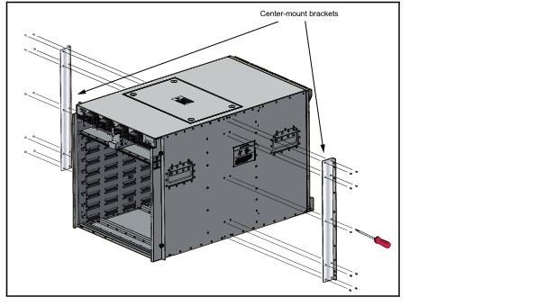
Figure 3-1: Attaching the Center-mount Brackets
Inserting the Switch into the Rack
Step 1 Move the chassis to the rack using a mechanical lift (Figure 3-2).
If modules are inserted in the chassis, use the lift carefully to avoid damaging any components.
Step 2 Lift the chassis into the rack. Position the flanges against the rack posts (Figure 3-2).

Figure 3-2: Lifting the Switch Chassis into the Two Post Rack
Step 3 Select mounting screws that fit your equipment rack.
A minimum of four screws is required on each side of the chassis. The accessory kit provides screws that fit many common equipment racks. When installing the switch into a rack with unthreaded post holes, nuts are also required to secure the switch to the rack posts.
Step 4 Attach the bracket flanges to the rack posts (Figure 3-3). Space the screws evenly along the flange.

Figure 3-3: Attaching Flanges to the Rack Post
After completing the two-post installation, proceed to Chapter 4.
Four-Post Rack Mount
The switch is mounted onto a four-post rack by assembling a shelf into the rack, then placing the switch on the shelf.
The accessory kit provides the following four-post mounting parts:
• 2 front brackets
• 4 shelf supports
• 2 back brackets (not needed for racks with threaded holes)
• left shelf
• right shelf
Figure B-1 displays the four-post mounting parts.
Assembling the Shelf
Step 1 Attach the front bracket and shelf support to the left front rack post, as shown in Figure 3-4. An up arrow is printed on the shelf support to indicate its proper orientation.
Unthreaded rack holes: Use the M6 screws and cage nuts supplied in the accessory kit.
Threaded rack holes: Attach the front bracket to the post with screws that can be threaded through the rack post. Secure the shelf support to the post with nuts that fit the screws threaded through the post.
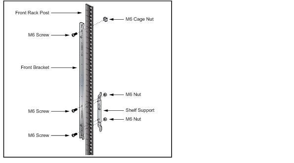
Figure 3-4: Left Front Post Assembly: Four Post Rack Mount
Step 2 Repeat step 1 on the right front rack post, assembling the parts at the same vertical level as those on the left rack post.
Step 3 Attach the shelf support and back bracket to the left rear post (Figure 3-5-left). The shelf support must be assembled at the same vertical level on the front and rear posts (Figure 3-5-right). An up arrow is printed on the shelf support to indicate its proper orientation.
Unthreaded rack holes: Attach the parts as displayed in Figure 3-5-left.
Threaded rack holes: Attach the shelf support to the post with screws that thread into the rack post. The back bracket is not required on threaded racks.

Figure 3-5: Left Rear Post Assembly and Shelf Support Orientation: Four Post Rack Mount
Step 4 Adjust the left shelf by sliding its components to fit between the front left and front rear rack posts, as shown in Figure 3-6.
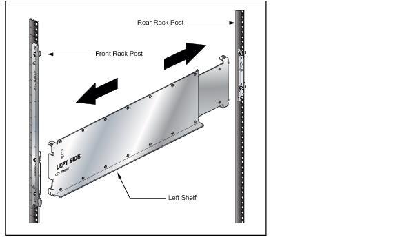
Figure 3-6: Adjusting the Left Shelf
Step 5 Lift the left shelf above the shelf supports installed on the left front and left rear rack posts (step 1 and step 3). Align the holes (Inset A) and hook (Inset B) with the stubs on the brackets. Lower the shelf such that the bracket stubs are inserted into the shelf holes and hook (Figure 3-7).
Press down firmly on the shelf to ensure it is seated securely on the rack posts.

Figure 3-7: Seating the Left Shelf
Step 6 Install the right shelf on the right front and right rear rack posts by repeating step 4 and step 5 to obtain the rack configuration shown in Figure 3-8.

Figure 3-8: Both Switch Shelves Installed
Inserting the Switch into the Rack
Step 1 Move the chassis to the rack using a mechanical lift (Figure 3-9).
If modules are inserted in the chassis, use the lift carefully to avoid damaging any components.
Step 2 Lift the chassis into the rack.

Figure 3-9: Lifting the Switch Chassis
Step 3 Secure the chassis by tightening the four thumbscrews on the front flanges into the rack posts (Figure 3-10).

Figure 3-10: Inserting the Switch onto the Rack Shelf
After completing the Four-Post Installation, proceed to Chapter 4.
Preparation
Site Selection
The following criteria should be considered when selecting a site to install the switch:
Floor Space: Install the switch in an area that provides adequate clearance for removing front and rear components. Figure 2-1 displays switch clearance requirements.

Figure 2-1: Switch Component Removal Footprint
• Temperature and Ventilation: For proper ventilation, install the switch where there is ample airflow to the front and back of the switch. The temperature should not go below 0° or exceed 40° C.
Important! To prevent the switch from overheating, do not operate it in an area where the ambient temperature exceeds 40°C (104°F).
Pour empêcher l’interrupteur de surchauffe, ne pas utiliser il dans une zone où la température ambiante est supérieure à 40° C (104° F).
Pour empêcher l’interrupteur de surchauffe, ne pas utiliser il dans une zone où la température ambiante est supérieure à 40° C (104° F).
• Airflow Orientation: The fans direct air from the front panel to the rear panel. Orient the front panel toward the cool aisle.
• Rack Space: Install the switch in a 19" rack or cabinet. The switch height is 11 RU (7508 / 7508E) or 7 RU (7504 / 7504E). The accessory kit provides mounting brackets for two-post and four-post racks.
When mounting the switch in a partially filled rack, load the rack from bottom to top, with the heaviest equipment at the bottom. Load the switch at the bottom if it is the only item in the rack.
• Power Requirements: The 7508 / 7508E switch requires two 200-240 VAC, 50 or 60 Hz, 20 A circuits. The 7504 / 7504E switches require one 200-240 VAC, 50 or 60 Hz, 20 A circuit.
Four circuits provide redundancy protection. The switch uses power cables that comply with IEC-320 and have a C19 plug. The accessory kit provides four IEC-320 C19 to C20 power cables, each two meters long.
Important! All power input plug-socket combinations must be accessible at all times; they provide the primary method of disconnecting power from the system.
Toutes les combinaisons de fiche-prise d’entrée de puissance doivent être accessibles en tout temps ; ils fournissent le principal moyen de coupure d’alimentation du système.
Toutes les combinaisons de fiche-prise d’entrée de puissance doivent être accessibles en tout temps ; ils fournissent le principal moyen de coupure d’alimentation du système.
• Other Requirements: Select a site where liquids or objects cannot fall onto the equipment and foreign objects are not drawn into the ventilation holes. Verify these guidelines are met:
• Clearance areas to the front and rear panels allow for unrestricted cabling.
• All front and rear panel indicators can be easily read.
• AC power cords can reach from the AC power outlet to the connectors on the front panel.
Important! Disconnecting power to all input sockets is required to completely power off the unit.
Coupure d’alimentation sur toutes les entrées il faut pouvoir complètement l’appareil hors tension.
Coupure d’alimentation sur toutes les entrées il faut pouvoir complètement l’appareil hors tension.
Tools and Parts Required for Installation
The following tools are required to install a modular switch:
• Mechanical device capable of lifting chassis being installed (Table 1-1).
• Adjustable wrench (provided)
• Phillips #2 screwdriver
• Phillips #3 screwdriver
Two-post rack mounts:
• Eight equipment rack screws (all two-post rack mounts).
• Eight equipment rack nuts (two-post rack mount with unthreaded rack post holes).
Four-port rack mounts:
• Eight equipment rack screws (four-post rack mount with threaded rack post holes).
Accessory kit provides rack screws for four-post rack mount with unthreaded rack post holes.
The accessory kit includes screws that fit many common equipment racks.
Electrostatic Discharge (ESD) Precautions
Observe these guidelines to avoid ESD damage when installing or servicing the switch.
• Assemble or disassemble equipment only in a static-free work area.
• Use a conductive work surface (such as an anti-static mat) to dissipate static charge.
• Wear a conductive wrist strap to dissipate static charge accumulation.
• Minimize handling of assemblies and components.
• Keep replacement parts in their original static-free packaging.
• Remove all plastic, foam, vinyl, paper, and other static-generating materials from the work area.
• Use tools that do not create ESD.
Overview
Scope
This guide is intended for properly trained service personnel and technicians who need to install the following Arista Networks Data Center Switches:
• DCS-7504 / 7504E
• DCS-7508 / 7508E
Important! Only qualified personnel should install, service, or replace this equipment.
Son élimination finale de ce produit doit être traitée selon toutes les lois et règlements nationaux.
Son élimination finale de ce produit doit être traitée selon toutes les lois et règlements nationaux.
Receiving and Inspecting the Equipment
Upon receiving the switch, inspect the shipping boxes and record any external damage. Retain packing materials if you suspect that part of the shipment is damaged; the carrier may need to inspect them.
If the boxes were not damaged in transit, unpack them carefully. Ensure that you do not discard any accessories that may be packaged in the same box as the main unit.
Inspect the packing list and confirm that you received all listed items. Compare the packing list with your purchase order. Appendix B provides a list of components included with the switch.
Installation Process
The following tasks are required to install and use the switch:
Step 1 Select and prepare the installation site (Section 2.1).
Step 2 Assemble the installation tools listed in Section 2.2.
Step 3 Attach the mounting brackets and install the switch in an equipment rack (Chapter 3).
Step 4 Connect the switch to the power source and network devices (Chapter 4).
Step 5 Configure the switch (Chapter 5).
Important! Class 1 Laser Product: This product has provisions to install Class 1 laser transceivers that provides optical coupling to the communication network. Once a Class 1 laser product is installed, the equipment is a Class 1 Laser Product (Appareil à Laser de Classe 1). The customer is responsible for selecting and installing the Class 1 laser transceiver and for insuring that the Class 1 AEL (Allowable Emission Limit) per EN/IEC 60825, CSA E60825-1, and Code of Federal Regulations 21 CFR 1040 is not exceeded after the laser transceiver have been installed. Do not install laser products whose class rating is greater than 1. Refer to all safety instructions that accompanied the transceiver prior to installation. Only Class 1 laser devices certified for use in the country of installation by the cognizant agency are to be utilized in this product.
Produit Laser de classe 1 : Ce produit a des dispositions pour installer des émetteurs-récepteurs de laser de classe 1 qui offre de couplage au réseau de communication optique. Une fois une classe 1 laser produit est installé, l’équipement est un produit Laser de classe 1 (Appareil à Laser de Classe 1). Le client est responsable pour sélectionner et installer l’émetteur/récepteur de laser de classe 1 et pour assurer que la classe 1 AEL (Limite d’émission admissible) par EN/IEC 60825, CSA E60825-1 et Code des règlements fédéraux 21 CFR 1040 ne soit pas dépassée après avoir installé l’émetteur/récepteur de laser. Ne pas installer des appareils à laser dont la cote de classe est supérieure à 1. Voir toutes les consignes de sécurité qui ont accompagné l’émetteur-récepteur avant l’installation.Seuls appareils laser de classe 1 certifiés pour une utilisation dans le pays d’installation par l’organisme compétent doivent être utilisées dans ce produit.
Produit Laser de classe 1 : Ce produit a des dispositions pour installer des émetteurs-récepteurs de laser de classe 1 qui offre de couplage au réseau de communication optique. Une fois une classe 1 laser produit est installé, l’équipement est un produit Laser de classe 1 (Appareil à Laser de Classe 1). Le client est responsable pour sélectionner et installer l’émetteur/récepteur de laser de classe 1 et pour assurer que la classe 1 AEL (Limite d’émission admissible) par EN/IEC 60825, CSA E60825-1 et Code des règlements fédéraux 21 CFR 1040 ne soit pas dépassée après avoir installé l’émetteur/récepteur de laser. Ne pas installer des appareils à laser dont la cote de classe est supérieure à 1. Voir toutes les consignes de sécurité qui ont accompagné l’émetteur-récepteur avant l’installation.Seuls appareils laser de classe 1 certifiés pour une utilisation dans le pays d’installation par l’organisme compétent doivent être utilisées dans ce produit.
Important! Ultimate disposal of this product should be handled in accordance with all national laws and regulations.
Son élimination finale de ce produit doit être traitée selon toutes les lois et règlements nationaux.
Son élimination finale de ce produit doit être traitée selon toutes les lois et règlements nationaux.
Safety Information
Refer to the Arista Networks document Safety Information and Translated Safety Warnings available at:
Obtaining Technical Assistance
Any customer, partner, reseller or distributor holding a valid Arista Service Contract can obtain technical support in any of the following ways:
• Email: This email address is being protected from spambots. You need JavaScript enabled to view it.. This is the easiest way to create a new service request.
Include a detailed description of the problem and the output of “show tech-support”.
A support case may be created through the support portal on our website. You may also download the most current software and documentation, as well as view FAQs, Knowledge Base articles, Security Advisories, and Field Notices.
• Phone: 866-476-0000 or 408-547-5502.
Important! No user serviceable parts inside. Refer all servicing to qualified service personnel.
Specifications
Table 1-1 lists the specifications of Arista Data Center switches covered by this guide. Table 1-2 lists power specifications of modular switch components.
|
|
DCS-7508 / DCS-7508E
|
DCS-7504 / DCS-7504E
|
|
Height
|
11U: 485 mm (19.1inches)
|
7 U: 312 mm (12.25 inches)
|
|
Width
|
483 mm (19 inches)
|
483 mm (19 inches)
|
|
Depth
|
762 mm (30 inches)
|
762 mm (30 inches)
|
|
Weight
|
136 kg (300 pounds)
|
95 kg (210 pounds)
|
|
Input Power (per circuit)
|
200/240 VAC, 50 or 60 hz, 20 A
|
200/240 VAC, 50 or 60 hz, 20 A
|
|
Input Power Circuits
|
2 to 4 circuits
|
1 to 4 circuits
|
|
Ambient Temperature
Storage Temperature Relative Humidity Altitude
|
0° to 40° C (32° to 104° F)
-40° to 70° C (-40° to 158° F) 5 to 90% 0 to 3,000 meters (0 to 10,000 feet) |
0° to 40° C (32°to 104° F)
-40° to 70° C (-40° to 158° F) 5 to 90% 0 to 3,000 meters (0 to 10,000 feet) |
|
Cooling
|
6600 W maximum
|
3300 W maximum
|
|
Module Type
|
Part Number
|
Power Draw (Typical / Maximum)
|
|
Supervisor Modules
|
DCS-7500E-SUP
|
180 W / 105 W
|
|
Line Card Modules
|
DCS-7500E-36Q-LC
DCS-7500E-72S-LC DCS-7500E-48S-LC DCS-7500E-12CM-LC DCS-7500E-6C2-LC DCS-7500E-12CQ-LC DCS-7500E-48T-LC DCS-7500E-6CFPX-LC |
450 W / 556 W
212 W / 305 W 197 W / 285 W 408 W / 495 W 300 W / 320 W 414 W / 486 W 318 W / 332 W 818 W / 875 W |
|
Fabric Modules
|
DCS-7504E-FM
DCS-7508E-FM |
80 W / 105 W
155 W / 195 W |
|
7500 Series System
|
DCS-7504 with DCS-7548S-LC
DCS-7508 with DCS-7548S-LC |
2124 W / 2778 W
3806 W / 4520 W |