ECMP
Adding ECMP
Describes how to add ECMP to new or existing VMs.
Subinterfaces are logical L3 interfaces commonly used in the L2/L3 boundary device. They enable the division of a single ethernet interface into multiple logical L3 interfaces, based on the incoming 802.1q tag (VLAN-ID).
For a subinterface to be operational on an Ethernet or port channel interface, the parent interface must be configured as a routed port and be administratively up, and a VLAN must be configured on the subinterface. If the parent interface goes down, all subinterfaces automatically go down as well, but will come back up with the same configuration once the parent interface is up.
Note, that a port channel should not contain Ethernet interfaces with subinterfaces configured on them, and that subinterfaces cannot be members of a port channel.
Subinterfaces are named by adding a period followed by a unique subinterface number to the name of the parent interface. Note that the subinterface number has no relation to the ID of the VLAN corresponding to the subinterface.
Configuring Routing Features on a Subinterface
Once a subinterface is created, the following features can be configured on it:
To create a subinterface on an Ethernet or port channel interface:
Step 1: Bring up the parent interface and ensure that it is configured as a routed port.
switch(config)#interface Ethernet1/1
switch(config-if-Et1/1)#no switchport
switch(config-if-Et1/1)#no shutdown
Step 2: Configure a VLAN on the subinterface. The encapsulation dot1q vlan command is also used for VLAN translation, but in this context it associates a VLAN with the subinterface.
switch(config-if-Et1/1)#interface Ethernet1/1.1
switch(config-if-Et1/1.1)#encapsulation dot1q vlan 100
Step 3: Configure an IP address on the subinterface (optional) and ensure that it is up.
switch(config-if-Et1/1)#ip address 10.0.0.1/24
switch(config-if-Et1/1)#no shutdown
switch(config-if-Et1/1)#
The Mirroring features allows the mirroring of source port packets in Rx, Tx and both directions to a local destination port. Mirroring with Greenspan feature allows mirroring of source packets in Rx direction on to GRE tunnel.
// Source port
switch(config)#monitor session <name> source <interface> [ rx | tx | both ] [ ip access-group <access-list-name>
// GREENSPAN destination
switch(config)#monitor session <name> destination tunnel mode gre source <ipAddress> destination <ipAddress> ttl <ttlValue> dscp <dscpValue>
// Port destination
switch(config)#monitor session <name> destination <interface>
switch(config)#monitor session r1 source Ethernet2 rx ip access-group a3
switch(config)#monitor session r1 destination tunnel mode gre source 75.75.75.75 destination 100.1.0.2
These two commands display the monitor and platform related mirroring information.
switch#show monitor session
Session r1
------------------------
Programmed in HW: Yes
Source Ports:
Rx Only: Et2(IPv4 ACL: a3)
Destination Ports:
statussource destTTL DSCP protoVRF fwd-drop
Gre1 :active 75.75.75.75 100.1.0.2 128 0 0x88be default no
next hop interfaces: Et5
switch#show platform sfe mirroring
Session: r1, mirrorGroup: 3, globalId: 0
srcIntf: Ethernet2, direction: Rx
tgtIntf: Gre1
encapType: Gre
Sfe module: Mir_r1_Rx_et2
Sfe srcIntf: Ethernet2, direction: Rx, gate: 0
Sfe tgtIntf: Ethernet5, gate: 1
Copy Success: 47523752, Fail: 0
Forward Success: 53109025, Fail: 0
The CloudEOS and vEOS supports the Dynamic Path Selection that selects the path for the traffic to optimize application performance in the enterprise deployments.
The enterprise network sites like Data centers, Branches, Public Cloud (AWS VPC, Azure VNet, and others) are connected through multiple SPs (MPLS, Internet, LTE). Enterprises deploy edge routers to connect these sites over the SP WAN networks and in some cases building GRE or IPsec tunnels between sites. For high availability reasons, there are at least two WAN networks or paths available between sites.
In the above example there are 5 paths, 1 MPLS path and are four paths through ISPs: ISP1, ISP1-ISP3, ISP2-ISP3, ISP2-ISP1. Different ISP have different costs, bandwidth, WAN characteristics, SLAs, and so on. This is ideal for users wanting to use various SPs in a cost effective manner without sacrificing application performance. The traditional enterprises use MPLS VPNs which provides a very good WAN characteristics such as (latency, etc), but, at a very high costs. Internet has been gaining adoption as an alternative WAN to MPLS that offers much higher bandwidth at lower costs. Also, MPLS VPNs are not available in all geographies. While ISPs are more readily available and at a lower cost, however, maintaining application performance for traffic across sites is a big problem because ISPs don’t offer a good SLAs. The traditional routing solutions do not address the requirements to optimize routing across WAN SP networks.
This section describes the functional overview of the Dynamic Path Selection feature. The below figure shows three routers in different sites interconnected through two SPs. In this example, Site 1 is a hub site and is connected to both Site 2 and Site 3. There are two paths between site1 to site 2 and two paths from site 1 to site 3.
A “path” represents a pair of interfaces, a source interface and a destination interface through which traffic can flow from site to site. For example, eth1/router1 -- eth1/router2 is a path. Note, that there could be many paths through the same egress interface. The “path” does not refer to the actual network path the packet takes through the SP network. There could be multiple network paths in SP network from customer’s edge router to another edge router. Also, the network paths could change. A path is unidirectional and path characteristics is tracked in each direction.
Selects the best path (destination IP and egress interface) to a destination for a given application. The algorithm has to select the best paths based on user specified priorities or constraints, and dynamically load balance flows across selected paths.
Note, that the routers are connected to two SPs in the above diagram. All customer prefixes are on the overlay network and if the VTEP IP r1addr and r2addr addresses are accessible through SP networks then the VXLAN overlay would work similar to the datacenter network. However the VTEP IP address is an internal IP address and is not routable over SP networks. While it is possible to make the VTEP IP address routable over MPS network (unlike ISP), since we want to dynamically load balance across SP networks we will not advertise the VTEP IP address over MPLS.
However, the WAN interfaces have SP routable IP address. For example, r1w1 IP address is routable on WAN1 and r1w2 IP address is routable on WAN2. The forwarding engine will replace the VTEP address on the packet based on the path selected before sending it to SP network.
Therefore for router 1:
For this, the router needs to know SP routable IP addresses through which it can reach each.
In the above figure there are five paths between the two sites:
Currently peer VTEP reachability needs to be configured statically, but, in future this is exchanged through BGP. BGP runs on the same loopback interface used as VXLAN source VREP interface in underlay.
The router tracks if the configured paths are available using routing updates, interface state and so on, and programs the available paths for forwarding.
The BGP traffic that is going between sites will all go through DPS interface and leverage path selection feature to ensure that the BGP traffic leverages all the path selection features. Different path selection policies can be setup for different control plane traffic types as for end applications.
Algorithm selects the path that meets all the criteria for an application. If there are multiple paths that meet then it load balances across the available paths. If none of the paths meet the criteria is it picks the one with the lowest loss rate.
The selected path for a given flow is then stored in flow cache. The chosen path is not reevaluated for constraints. Packets from that flow will take the same path even if the path characteristics no longer meet the user specified criteria.
Events that trigger the re-selection of path for a flow are as shown below:
Path Telemetry feature provides the ability to determine WAN path state and measure its characteristics including latency (one way delay), jitter, packet loss rate and throughput.
The outer IP header uses the WAN IP addresses on local and peer WAN interfaces of the path. IP header is followed by a UDP header where the destination port is set to be 4793 by default or to be the port number configured by user in CLI. When IPsec is enabled, destination port is set to be 4500. A path telemetry header is inserted in between of UDP/ESP header and the inner IP packet for path characteristics measurement purpose.
Path telemetry uses keepalive and feedback packets to determine path state. It sends out keepalive periodically (once per second) and if it receives peer’s feedback packet, the path is considered as active and its characteristics is measured. Accordingly, if feedback packet is not received within a certain period of time (for 5 keepalive we sent), the path is considered as inactive and is not used for path selection.
This section describes the commands to configure and verify the Dynamic Path Selection feature.
A “path” represents a pair of interfaces (or their IP addresses), a source interface and a destination interface through which traffic can flow from site to site.
For example, in the above figure there are two paths from Router1 to Router2
However, some of the paths are crossing ISPs, for example, 1.1.1.1 -- 4.4.4.4 is going from router1 through ISP1, ISP2 to router2. In some customer scenarios ISP2 could be an LTE SP and could be purely as a backup in case ISP1 fails. In this case the paths 1.1.1.1 -- 4.4.4.4 and 2.2.2.2 -- 3.3.3.3 should not be used.
Path-group similar to nexthop-group is used to group the paths in order to
Path group commands are configured under “router path-selection” as shown below. The commands are explained in the subsections.
router path-selection
path-group <group-name>
local interface <intf-name>
## more local interface commands
## that belong to the same path-group, eg Internet
peer static router-ip <ip-address>
ipv4 address <ip-addr1>
## more IP addresses through which the router can be reached
The router-IP is the same as the VTEP-IP. local is used to configure the local WAN IP address or interface part of the path-group. Peer is used to configure the remote VTEP reachability statically.
Each combination of peer and local IP address is a potential path. If routing resolves the remote IP through a local interface then that local-remote IP pair becomes a real path that is used for forwarding.
In the topology in the above figure two groups are defined.
Further if paths need to be restricted through the Internet, the Internet groups can be divided into more groups. For example, the customer can define ISP1 and ISP2-ISP3 as separate groups create 2 Internet paths instead of 4.
router path-selection path-group <name>
name:name of the path group
Example
switch(config)#router path-selection
switch(config-dynamic-path-selection)#
switch(config-dynamic-path-selection)#path-group mpls
path-group <name> local interface <intf-name>
local interface: is used to configure the local WAN interface part of the path-group. The IP addresses assigned to the WAN interface is used as WAN IP. Multiple interfaces can be specified. For example, if there are two ISP connections.
Example
In the above deployment: ether1 is part of MPLS path-group.
switch(config-dynamic-path-selection)#path-group mpls
switch(config-path-group-mpls)#local interface ether1
Ethernet 2 and 3 are part of Internet path-group
switch(config-dynamic-path-selection)#path-group internet
switch(config-path-group-internet)#local interface ether2
switch(config-path-group-internet)#local interface ether3
path-group <name> peer static router-ip <ip-address>ipv4 address <ip-addr1>ipv4 address <ip-addr2> ## more IP addresses through which the router can be reached
peer static is used to configure the remote VTEP reachability statically via routable IP addresses over the SP network. The router-IP is the VTEP IP address. In the case of Internet, the routable IP address is a public IP address. In the case of MPLS it is Enterprise specific private IP address that the MPLS provider knows how to reach. Typically customer edge routers (CEs) are configured to exchange subnets by running eBGP to the SP’s PE router.
Example
switch(config-dynamic-path-selection)#path-group mpls
switch(config-path-group-mpls)#peer static router-ip 10.2.2.2
switch(config-peer-router-ip-10.2.2.2-mpls)#ipv4 address 172.16.2.1
For the Internet path group Router2’s router IP 10.2.2.2 is reachable via two IP addresses only via ISP1 3.3.3.3 and another through ISP2 4.4.4.4
switch(config-dynamic-path-selection)#path-group internet
switch(config-path-group-internet)#peer static router-ip 10.2.2.2
switch(config-peer-router-ip-10.2.2.2-internet)#ipv4 address 3.3.3.3
switch(config-peer-router-ip-10.2.2.2-internet)#ipv4 address 4.4.4.4
It is important to note that once local and remote IP addresses are specified for a path-group then all combinations of local and remote IP address is a potential path for load balancing.
Example
switch(config)#router path-selection
switch(config-dynamic-path-selection)#path-group mpls
switch(config-path-group-mpls)#local interface et1
switch(config-path-group-mpls)#peer static router-ip 10.2.2.2
switch(config-peer-router-ip-10.2.2.2-mpls)#ipv4 address 172.16.2.1
switch(config-peer-router-ip-10.2.2.2-mpls)#path-group internet
switch(config-path-group-internet)#local interface et2
switch(config-path-group-internet)#local interface et3
switch(config-path-group-internet)#peer static router-ip 10.2.2.2
switch(config-peer-router-ip-10.2.2.2-internet)#ipv4 address 3.3.3.3
switch(config-peer-router-ip-10.2.2.2-internet)#ipv4 address 4.4.4.4
The paths defined are
MPLS path - 172.16.1.1 -- 172.16.2.1
4 Internet paths
1.1.1.1 -- 3.3.3.3
1.1.1.1 -- 4.4.4.4
2.2.2.2 -- 3.3.3.3
2.2.2.2 -- 4.4.4.4
However if ISP2 is a LTE and the customer does not want paths to cross over from ISP1 to LTE then the configuration should be
switch(config)#router path-selection
switch(config-dynamic-path-selection)#path-group mpls
switch(config-path-group-mpls)#local interface et1
switch(config-path-group-mpls)#peer static router-ip 10.2.2.2
switch(config-peer-router-ip-10.2.2.2-mpls)#ipv4 address 172.16.2.1
switch(config-peer-router-ip-10.2.2.2-mpls)#path-group internet
switch(config-path-group-internet)#local interface et2
switch(config-path-group-internet)#peer static router-ip 10.2.2.2
switch(config-peer-router-ip-10.2.2.2-internet)#ipv4 address 3.3.3.3
switch(config-peer-router-ip-10.2.2.2-internet)#path-group lte
switch(config-path-group-lte)#local interface et3
switch(config-path-group-lte)#peer static router-ip 10.2.2.2
switch(config-peer-router-ip-10.2.2.2-lte)#ipv4 address 4.4.4.4
In the above case the paths are
MPLS path - 172.16.1.1 -- 172.16.2.1
Internet path 1.1.1.1 -- 3.3.3.3
LTE path 2.2.2.2 -- 4.4.4.4.
For DPS paths and EVPN routes to be exchanged we need to configure VXLAN with a private IP address of a loopback interface and DPS interface should be configured as L3 interface. Please note that the configuration for DPS interface has to be split up and configured under two interfaces VXLAN1 and et100. In future they are replaced with one single DPS interface.
For the DPS interface add any private IP address to make it an Layer 3 interface. However, the assigned IP address is not used for routing.
interface Ethernet100 no switchport ip address 11.0.0.1/24
switch(config)#interface ethernet 100
switch(config-if-Et100)#no switchport
switch(config-if-Et100)#ip address 11.0.0.1/24
In the example below 1.1.1.1 is a private IP which is configured in loopback 0 interface is used as VXLAN source interface.
Example
switch(config)#interface loopback 0
switch(config-if-Lo0)#ip address 1.1.1.1/32
switch(config-if-Lo0)#interface vxlan1
switch(config-if-Vx1)#vxlan source-interface loopback 0
switch(config-if-Vx1)#vxlan udp-port 4789
switch(config-if-Vx1)#vxlan vrf vrf1 vni 100
BGP runs on the same loopback IP as VXLAN source interface IP. In the above example BGP runs on ips 1.1.1.1, 2.2.2.2, and 3.3.3.3 on each peer.
For underlay routing add the remote peer routes via DPS interface and statically add an ARP entry for remote peer. In future versions of EOS the underlay routing also be handled by BGP.
Example
switch(config)#ip route 2.2.2.2/32 ethernet 100
switch(config)#ip route 3.3.3.3/32 ethernet 100
switch(config)#arp 2.2.2.2 00:00:33:02:00:00 arpa
switch(config)#arp 3.3.3.3 00:00:33:03:00:00 arpa
The above configuration makes the peers reachable via DPS.
The policies for the path groups are applied on all the paths in the group. The following policy is supported:
Applying IPsec to the group will enable encryption on all the paths in the group as per the applied IPsec profile. This policy is used to encrypt all Internet paths. This configuration simplifies IPsec configuration as the customer does not have to specify what traffic to encrypt.
path-group <name> ipsec profile <ipsec-profile-name> Applying IPsec profile will cause all the paths in the path group to be encrypted based on the algorithms and authentication mechanisms as per the profile.
Load balancing policy is configured under router path-selection as shown.
router path-selection load-balance policy <name> latency <milliseconds> jitter <milliseconds> loss-rate <0.00-100.00 percentage> path-group <group-name> [ priority <number>] path-group <group-name> The commands are explained in the following subsections.
router path-selection load-balance policy <name> path-group <group-name> path-group <group-name>
When multiple path-groups are specified flows are load balanced across all the paths in the specified path-groups.
Example
switch(config)#router path-selection
switch(config-dynamic-path-selection)#load-balance policy best-effort
switch(config-load-balance-policy-best-effort)#path-group mpls
switch(config-load-balance-policy-best-effort)#path-group internet
router path-selection load-balance policy <name> latency <milliseconds> jitter <milliseconds> loss-rate <0.00-100.00 percentage>
Latency, jitter and loss-rate constraints can be specified for path selection. There can be more than one path that meets the constraints in which case the flows are load balanced across all the selected paths. All constraints need to be met. If none of the paths meet the constraints, then the path with the lowest loss rate is chosen as the best path.
Example
switch(config-path-selection)#load-balance policy voice
switch(config-load-balance-policy-voice)#path-group mpls
switch(config-load-balance-policy-voice)#path-group internet
switch(config-load-balance-policy-voice)#latency 50
switch(config-load-balance-policy-voice)#loss-rate 1
In this case, the traffic is load balanced across all the paths that meet the constraints. If none matches then the traffic is sent to the best path.
router path-selection load-balance policy <name> path-group <group-name> [ priority <number>] path-group <group-name>
Preference can be specified for path-groups. Flows are load balanced based on path group priority. The lower the number the higher the priority is given to the path group. If not specified, default policy is 1 (highest). If multiple path groups in the same load-balance profile have same priority traffic will be load balanced among them. If no paths in a path-group are available then paths from the next lower priority is considered. Paths may not be available because of the following reasons:
Example
switch(config-dynamic-path-selection)#load-balance policy voice
switch(config-load-balance-policy-voice)#path-group mpls
switch(config-load-balance-policy-voice)#path-group internet
When MPLS path is down then all the existing flows are forwarded through Internet paths. When MPLS path is up again, all the new flows are forwarded through MPLS paths.
The existing commands in EOS are as shown below.
application traffic recognition application ipv4 http-8080 { protocol <proto> [ destination-port { <port_num> | <port-range> } ] } protocol tcp destination-port 8080 protocol tcp destination-port 8000 application ipv4 app2-service protocol tcp destination-port 8001-8080
Applications is specified either with custom signatures specified using the application configuration as shown above or can be imported from a DPI engine. Application configuration might have to be extended to address the path-selection use case.
Applications can be grouped and other attributes like the traffic class can be specified using application-profile as below.
application traffic recognition application-profile <app-xyz> application <app-name-1> application <app-name-2>
Example
switch(config)#application traffic recognition
switch(config-app-recognition)#application-profile gold
switch(config-app-profile-gold)#application voice
switch(config-app-profile-gold)#traffic-policies
“bronze” profile for best effort
switch(config-app-recognition)#application-profile bronze
switch(config-app-profile-bronze)#application best-effort
switch(config-app-profile-bronze)#traffic-policies
The load balancing policy can be specified based on the application.
router path-selection policy <dps-policy-name> <rule key> application-profile <profile-name> load-balance <load balance policy name><rule key> application-profile <profile-name> load-balance <load balance policy name>
Sequence numbers are required since a flow can potentially match multiple application profiles. Also, we have “set load-balance” as a sub-mode so we can add other actions for “match application-profile”.
switch(config)#router path-selection
switch(config-dynamic-path-selection)#policy dynamic
switch(config-policy-dynamic)#10 application-profile voice
switch(config-policy-rule-key-10-dynamic)#load-balance voice
switch(config-policy-rule-key-10-dynamic)#20 application-profile best
switch(config-policy-rule-key-20-dynamic)#load-balance best
All traffic going from site to site will go through VTI interfaces and is VXLAN encapsulated. Different classification and path selection policies are specified for each VRF. For example, the test VRF can have simple application classification and load balancing policy.
router path-selection vrf <vrf-name> path-selection-policy <policy-name>
VRF “all” can be specified to apply policy on all VRFs. In case both “all” and per VRF policy is specified, only the per VRF policy is applied.
The policy (classification and load balancing) needs to be applied to the datapath once it is determined that traffic is going from site to site. This is done to avoid the classification overhead for LAN to LAN traffic. When policy is applied on a VRF it is actually applied on the egress direction on the hidden SVI interface for the VTI (VXLAN tunnel interface). If there is no VTI configured then this policy is ignored.
When policy is applied on a VRF it is actually applied on the egress direction on the hidden SVI interface for the VTI (VXLAN tunnel interface) as shown below. If there is no VTI configured then this policy is ignored.
switch(config)#router path-selection
switch(config-dynamic-path-selection)#vrf red
switch(config-vrf-red)#path-selection-policy production
switch(config-vrf-red)#
By default, the path telemetry protocol uses 4793 as the destination UDP port number for encapsulation purpose. The below command is used to configure the UDP port for DPS.
router path-selection encapsulation path-telemetry udp port <number>
switch(config)#router path-selection
switch(config-dynamic-path-selection)#encapsulation path-telemetry udp port 4794
switch#application traffic recognition
switch(config-app-recognition)#application-profile platinum
switch(config-app-profile-platinum)#application voice
switch(config-app-profile-platinum)#application skype-voice
switch(config-app-profile-platinum)#application-profile bronze
switch(config-app-profile-bronze)#application scp
switch(config-app-profile-bronze)#application ftp
switch(config-app-profile-bronze)#router path-selection
switch(config-dynamic-path-selection)#path-group mpls
switch(config-path-group-mpls)#local interface et1
switch(config-path-group-mpls)#peer static router-ip 10.2.2.2
switch(config-peer-router-ip-10.2.2.2-mpls)#ipv4 address 172.16.2.1
switch(config-peer-router-ip-10.2.2.2-mpls)#path-group internet
switch(config-path-group-internet)#local interface et2
switch(config-path-group-internet)#local interface et3
switch(config-path-group-internet)#peer static router-ip 10.2.2.2
switch(config-peer-router-ip-10.2.2.2-internet)#ipv4 address 3.3.3.3
switch(config-peer-router-ip-10.2.2.2-internet)#ipv4 address 4.4.4.4
switch(config-dynamic-path-selection)#load-balance policy voice
switch(config-load-balance-policy-voice)#latency 50
switch(config-load-balance-policy-voice)#path-group mpls
switch(config-load-balance-policy-voice)#path-group internet priority 2
switch(config-load-balance-policy-voice)#load-balance policy best-effort
switch(config-load-balance-policy-best-effort)#path-group mpls
switch(config-load-balance-policy-best-effort)#path-group internet
switch(config-load-balance-policy-best-effort)#load-balance policy default
switch(config-load-balance-policy-default)#path-group internet
switch(config-load-balance-policy-default)#policy dynamic
switch(config-policy-dynamic)#10 application-profile platinum
switch(config-policy-rule-key-10-dynamic)#load-balance voice
switch(config-policy-rule-key-10-dynamic)#20 application-profile bronze
switch(config-policy-rule-key-20-dynamic)#load-balance best-effort
switch(config-dynamic-path-selection)#policy dynamic
switch(config-policy-dynamic)#interface ethernet 100
switch(config-if-Et100)#no switchport
switch(config-if-Et100)#ip address 11.0.0.1/24
switch(config-if-Et100)#interface loopback 0
switch(config-if-Lo0)#ip address 10.1.1.1/32
switch(config-if-Lo0)#interface vxlan 1
switch(config-if-Vx1)#vxlan source-interface loopback 0
switch(config-if-Vx1)#vxlan udp-port 4789
switch(config-if-Vx1)#vxlan vrf vrf1 vni 100
switch(config-if-Vx1)#ip route 10.2.2.2/32 ethernet 100
switch(config)#arp 10.2.2.2 00:00:33:02:00:00 arpa
switch(config)#
Site-1
switch(config)#router path-selection
switch(config-dynamic-path-selection)#path-group 1
switch(config-path-group-1)#local interface ethernet 5
!
switch(config-path-group-1)#peer static router-ip 22.22.22.22
switch(config-peer-router-ip-22.22.22.22-1)#ipv4 address
8.0.1.5
!
switch(config-peer-router-ip-22.22.22.22-1)#load-balance
policy policy-1
switch(config-load-balance-policy-policy-1)#path-group 1
!
switch(config-load-balance-policy-policy-1)#policy policy-1
switch(config-policy-policy-1)#default-match
switch(config-policy-default-rule-policy-1)#load-balance
policy-1
!
switch(config-policy-default-rule-policy-1)#vrf default
switch(config-vrf-default)#path-selection-policy policy-1
!
switch(config-dynamic-path-selection)#vrf et1
switch(config-vrf-et1)#path-selection-policy policy-1
!
switch(config-vrf-et1)#vrf instance et1
switch(config-vrf-et1)#interface ethernet 1
switch(config-if-Et1)#description LAN-interface
switch(config-if-Et1)#no switchport
switch(config-if-Et1)#ip address 4.0.1.5/24
!
switch(config)#vrf instance et1
switch(config-vrf-et1)#interface ethernet 1
switch(config-if-Et1)#description LAN-interface
switch(config-if-Et1)#no switchport
switch(config-if-Et1)#ip address 4.0.1.5/24
!
switch(config-if-Et1)#interface ethernet 5
switch(config-if-Et5)#description WAN-Interface
switch(config-if-Et5)#no switchport
switch(config-if-Et5)#ip address 5.0.1.5/24
!
switch(config-if-Et5)#interface ethernet 100
switch(config-if-Et100)#no switchport
switch(config-if-Et100)#ip address 10.0.0.2/24
!
switch(config-if-Et100)#interface loopback 1
switch(config-if-Lo1)#ip address 11.11.11.11/32
!
switch(config-if-Lo1)#interface vxlan 1
switch(config-if-Vx1)#vxlan source-interface loopback 1
switch(config-if-Vx1)#vxlan udp-port 4789
switch(config-if-Vx1)#vxlan vrf et1 vni 5
!
switch(config-if-Vx1)#ip route 22.22.22.22/32 ethernet 100
!
switch(config)#arp 22.22.22.22 22:22:22:22:22:22 arpa
!
switch(config)#ip routing
switch(config)#ip routing vrf et1
!
switch(config)#router bgp 32
switch(config-router-bgp)#neighbor 5.0.1.1 remote-as 501
switch(config-router-bgp)#neighbor 5.0.1.1 maximum-routes
12000
switch(config-router-bgp)#neighbor 22.22.22.22 remote-as 43
switch(config-router-bgp)#neighbor 22.22.22.22 update-source
loopback 1
switch(config-router-bgp)#neighbor 22.22.22.22 ebgp-multihop
switch(config-router-bgp)#neighbor 22.22.22.22 send-community
extended
switch(config-router-bgp)#neighbor 22.22.22.22 maximum-routes
12000
switch(config-router-bgp)#redistribute static
!
switch(config-router-bgp)#address-family evpn
switch(config-router-bgp-af)#neighbor 22.22.22.22 activate
!
switch(config-router-bgp-af)#exit
switch(config-router-bgp)#address-family ipv4
switch(config-router-bgp-af)#no neighbor 22.22.22.22 activate
switch(config-router-bgp-af)#exit
!
switch(config)#router bgp 32
switch(config-router-bgp)#vrf et1
switch(config-router-bgp-vrf-et1)#rd 4.0.1.5:0
switch(config-router-bgp-vrf-et1)#route-target import evpn
9.0.1.5:0
switch(config-router-bgp-vrf-et1)#route-target export evpn
4.0.1.5:0
switch(config-router-bgp-vrf-et1)#router-id 4.0.1.5
switch(config-router-bgp-vrf-et1)#network 4.0.1.0/24
switch(config-router-bgp-vrf-et1)#network 50.0.0.0/24
switch(config-router-bgp-vrf-et1)#exit
switch(config-router-bgp)#exit
switch(config)#
---------------------------------------------------------------------------------
Site-2
switch(config)#router path-selection
switch(config-dynamic-path-selection)#path-group 1
switch(config-path-group-1)#local interface ethernet 1
!
switch(config-path-group-1)#peer static router-ip 11.11.11.11
switch(config-peer-router-ip-11.11.11.11-1)#ipv4 address
5.0.1.5
!
switch(config-peer-router-ip-11.11.11.11-1)#load-balance
policy policy-1
switch(config-load-balance-policy-policy-1)#path-group 1
!
switch(config-load-balance-policy-policy-1)#policy policy-1
switch(config-policy-policy-1)#default-match
switch(config-policy-default-rule-policy-1)#load-balance
policy-1
!
switch(config-policy-default-rule-policy-1)#vrf default
switch(config-vrf-default)#path-selection-policy policy-1
!
switch(config-dynamic-path-selection)#vrf et5
switch(config-vrf-et5)#path-selection-policy policy-1
!
switch(config-vrf-et5)#vrf instance et5
switch(config-vrf-et5)#interface ethernet 1
switch(config-if-Et1)#description WAN-Interface
switch(config-if-Et1)#no switchport
switch(config-if-Et1)#ip address 8.0.1.5/24
!
switch(config)#vrf instance et5
switch(config-vrf-et5)#interface ethernet 5
switch(config-if-Et5)#description LAN-interface
switch(config-if-Et5)#no switchport
switch(config-if-Et5)#ip address 9.0.1.5/24
!
switch(config-if-Et5)#interface ethernet 100
switch(config-if-Et100)#no switchport
switch(config-if-Et100)#ip address 10.0.0.1/24
!
switch(config-if-Et100)#interface loopback 1
switch(config-if-Lo1)#ip address 22.22.22.22/32
!
switch(config-if-Lo1)#interface vxlan 1
switch(config-if-Vx1)#vxlan source-interface loopback 1
switch(config-if-Vx1)#vxlan udp-port 4789
switch(config-if-Vx1)#vxlan vrf et5 vni 5
!
switch(config-if-Vx1)#ip route 11.11.11.11/32 ethernet 100
!
switch(config)#arp 11.11.11.11 11:11:11:11:11:11 arpa
!
switch(config)#ip routing
switch(config)#ip routing vrf et5
!
switch(config)#router bgp 43
switch(config-router-bgp)#maximum-paths 16
switch(config-router-bgp)#neighbor 8.0.1.1 remote-as 701
switch(config-router-bgp)#neighbor 8.0.1.1 maximum-routes
12000
switch(config-router-bgp)#neighbor 11.11.11.11 remote-as 32
switch(config-router-bgp)#neighbor 11.11.11.11 update-source
loopback 1
switch(config-router-bgp)#neighbor 11.11.11.11 ebgp-multihop
switch(config-router-bgp)#neighbor 11.11.11.11 send-community
extended
switch(config-router-bgp)#neighbor 11.11.11.11 maximum-routes
12000
!
switch(config-router-bgp)#address-family evpn
switch(config-router-bgp-af)#neighbor 11.11.11.11 activate
switch(config-router-bgp-af)#exit
!
switch(config-router-bgp)#address-family ipv4
switch(config-router-bgp-af)#no neighbor 11.11.11.11 activate
switch(config-router-bgp-af)#exit
!
switch(config)#router bgp 40
switch(config-router-bgp)#vrf et5
switch(config-router-bgp-vrf-et5)#rd 9.0.1.5:0
switch(config-router-bgp-vrf-et5)#route-target import evpn
4.0.1.5:0
switch(config-router-bgp-vrf-et5)#route-target export evpn
9.0.1.5:0
switch(config-router-bgp-vrf-et5)#router-id 9.0.1.5
switch(config-router-bgp-vrf-et5)#network 9.0.1.0/24
switch(config-router-bgp-vrf-et5)#network 51.0.0.0/24
switch(config-router-bgp-vrf-et5)#exit
switch(config-router-bgp)#exit
switch(config)#
The following show commands are used to verify the various information of the Dynamic Path Selection application.
These two show commands provide path telemetry status:
show monitor telemetry path characteristics [ detail ][ destination DSTIP ][ path-name NAME ][ peer PEERIP ] [ source SRCIP ] [ traffic-class TC ]
show monitor telemetry path counters [ detail ][ destination DSTIP ][ path-name NAME ][ peer PEERIP ] [ source SRCIP ][ traffic-class TC ]
Example
switch#show monitor telemetry path characteristics
PathName TrafficClassTxStateLatency(ms)Jitter(ms)Throughput(Mbps)LossRate(%)
path10 active 3.520 1.12210.000.01
path20 active 35.2202.33010.001.01
switch#show monitor telemetry path characteristics detail
Peer: 10.1.10.5
PathName: path1
Source: 156.142.20.23, Destination: 156.142.40.21
Traffic Class: 0
TxState: active
Latency: 3.520 ms
Jitter:1.122 ms
Throughput: 10.00 Mbps
LossRate: 0.01 %
PathName: path2
Source: 156.142.20.24, Destination: 156.142.40.22
Traffic Class: 0
TxState: active
Latency: 35.220 ms
Jitter:2.330ms
Throughput: 1000 Mbps
LossRate: 1.01 %
switch#show monitor telemetry path counters
PathName TrafficClassInBytesInPktsInPktsDropOutBytesOutPktsOutPktsDrop
path10 455330010220 5341333 7520
path20 455330010220 5341333 7520
kvs17-b10#show monitor telemetry path counters detail
Peer: 10.1.10.5
PathName: path1
Source: 156.142.20.23, Destination: 156.142.40.21
Traffic Class: 0
InBytes: 4553300
InPkts: 1022
InPktsDrop: 0
OutBytes: 5341333
OutPkts: 752
OutPktsDrop: 0
Both path characteristics and path counters show results can be filtered by path name, destination IP, source IP, remote IP and traffic class. And both of them have detail version output and brief version output, default version is brief version as shown.
The following IPsec show commands filter IPsec connections based on path name and remote IP address. The IPsec show results are filtered using the following options like Tunnel, Detail, Path, and VRF.
switch#show ip security connection path
NameSource Dest Status Uptime InputOutput Rekey Time
Path1 ip1ip3Established22 minutes 0 bytes0 bytes34 minutes
0 pkts 0 pkts
Path2 ip2ip3Established22 minutes 0 bytes0 bytes34 minutes
0 pkts 0 pkts
Path2 ip5ip6Established22 minutes 0 bytes0 bytes34 minutes
0 pkts 0 pkts
switch#show ip security connection path name path1
NameSource Dest Status Uptime InputOutput Rekey Time
Path1 ip1ip3Established22 minutes 0 bytes0 bytes34 minutes
0 pkts 0 pkts
switch#show ip security connection path peer ip3
NameSource Dest Status Uptime InputOutput Rekey Time
Path1 ip1ip3Established22 minutes 0 bytes0 bytes34 minutes
0 pkts0 pkts
Path2 ip2ip3Established22 minutes 0 bytes0 bytes34 minutes
0 pkts0 pkts
These counters display the statistics of load balancing based on application profile, overlay VRF and remote node IP:
show path-selection load-balance counter [ detail ] [ application-profile APPNAME ] [ peer PEERIP ] [ vrf VRFNAME]
show path-selection application counters[ application-profile APPNAME ] [ peer PEERIP ] [ vrf VRFNAME ]
switch#show path-selection load-balance counters
AppProfileVrfPeer PathGroupPath FlowsThroughput(Mbps)
app1vrf1 11.0.1.1 transit0 path200.00
app2vrf1 11.0.1.1 transit1 path100.00
default_app default11.0.1.1 transit0 path200.00
transit1 path100.00
switch#show path-selection load-balance counters detail
AppProfileVrfPeer PathGroupPath FlowsThroughput(Mbps) OutBytes OutPkts
app1vrf1 11.0.1.1 transit0 path200.00 00
app2vrf1 11.0.1.1 transit1 path100.00 00
default_app default11.0.1.1 transit0 path200.00 1052 17
transit1 path100.00 1321 17
switch#show path-selection application counters
AppProfile VRF PeerThroughput OutBytes OutPackets
SilverRed 10.0.0.1153000 15
Output of both show path-selection load-balance counters and show path-selection application counters can be filtered by application-profile name, peer IP address and vrf name.
The following commands clears the DPS related counters:
Clear load balancing and application counters:
clear path-selection counters Clear path telemetry counters:
clear monitor telemetry path counters
In order for DPS to work, the following needs to be working.
The vEOS Router provides robust support for the use of IPsec to establish and maintain IPsec tunnels for secure or encrypted communications between virtual router peer instances as well as virtual peer instances to non-virtual routers.
The vEOS Router supports the use of two basic types of IPsec tunnels. The tunnel types are determined based on the encapsulation mode.
The vEOS Router supports the use of NAT-Traversal to communicate with the remote peer virtual router. To ensure that the tunnel configuration between the vEOS Router and peer router is successful, make sure that vEOS Router tunnel configuration meets the requirements for using NAT.
The vEOS Router enables you to establish and maintain GRE-over-IPsec and VTI IPsec tunnels for secure or encrypted communications between peer vEOS Router instances.
The vEOS Router enables you to establish and maintain IPsec tunnels for secure or encrypted communications between vEOS Router instances and third party peer router instances.
The CloudEOS and vEOS Router supports the use of two basic types of IPsec tunnels. The tunnel types are determined based on the encapsulation mode.
The supported tunnel types are:GRE-over-IPsec
VTI IPsec
The CloudEOS and vEOS Router supports the use of NAT-Traversal to communicate with the remote peer behind a NAT. Configure the tunnel source with the outgoing interface IP address on the router.
Flow ParallelizationIf the IPsec session is established without the feature enabled, complete the following tasks:
Use the vEOS Router to establish and maintain IPsec tunnels between peer vEOS Router instances in different topologies of varying complexity.
The diagram below represents a basic IPsec tunnel configuration in which vEOS Router instances are using an IPsec tunnel.
The vEOS Router establishes and maintains IPsec tunnels for secure or encrypted communications between vEOS Router instances and third party devices peer router instances.
Use this procedure to configure GRE-over-IPsec or VTI IPsec tunnels on peer CloudEOS and vEOS Router instances.
The procedure provides all of the steps required to set up either GRE-over-IPsec or VTI IPsec tunnels. Most of the steps are the same for both tunnel types (steps 1 through 6 are the same). Step 7 is the step to select the tunnel type.
Procedure
Complete the following steps to configure GRE-over-IPsec or VTI IPsec tunnels on CloudEOS and vEOS Router instances. This configuration will be the default IKE version 2 procedure.
The following examples show the running configurations for two CloudEOS and vEOS Router instances (CloudEOS and vEOS1 and CloudEOS and vEOS2). The instances are the tunnel endpoints of a GRE-over-IPsec tunnel.
ip security
ike policy ikebranch1
integrity sha256
dh-group 15
!
sa policy sabranch1
sa lifetime 2
pfs dh-group 14
!
profile hq
mode tunnel
ike-policy ikebranch1
sa-policy sabranch1
connection add
shared-key keyAristaHq
dpd 10 50 clear
!
interface Tunnel1
mtu 1404
ip address 1.0.3.1/24
tunnel mode gre
tunnel source 1.0.0.1
tunnel destination 1.0.0.2
tunnel ipsec profile hq
!
interface Ethernet1
no switchport
ip address 1.0.0.1/24
!
ip security
ike policy ikebranch1
integrity sha256
dh-group 15
!
ike policy ikebranch2
dh-group 15
version 1
local-id 200.0.0.1
!
ike policy ikedefault
!
sa policy sabranch1
sa lifetime 2
pfs dh-group 14
!
profile hq
mode tunnel
ike-policy ikebranch1
sa-policy sabranch1
connection start
shared-key keyAristaHq
dpd 10 50 clear
!
interface Tunnel1
mtu 1404
ip address 1.0.3.2/24
tunnel mode gre
tunnel source 1.0.0.2
tunnel destination 1.0.0.1
tunnel ipsec profile hq
!
interface Ethernet2
no switchport
ip address 1.0.0.2/24
!
The following examples show the running configurations for two CloudEOS and vEOS Router instances (CloudEOS and vEOS1 and CloudEOS and vEOS2). The instances are the tunnel endpoints of a VTI IPsec tunnel.
ip security
ike policy ikebranch1
integrity sha256
dh-group 15
!
sa policy sabranch1
sa lifetime 2
pfs dh-group 14
!
profile hq
mode tunnel
ike-policy ikebranch1
sa-policy sabranch1
connection add
shared-key keyAristaHq
dpd 10 50 clear
!
interface Ethernet1
no switchport
ip address 1.0.0.1/24
!
interface Management1
ip address dhcp
!
interface Tunnel1
mtu 1404
ip address 1.0.3.1/24
tunnel mode ipsec
tunnel source 1.0.0.1
tunnel destination 1.0.0.2
tunnel ipsec profile hq
!
ip security
ike policy ikebranch1
integrity sha256
dh-group 15
!
ike policy ikebranch2
dh-group 15
version 1
local-id 200.0.0.1
!
ike policy ikedefault
!
sa policy sabranch1
sa lifetime 2
pfs dh-group 14
!
profile hq
mode tunnel
ike-policy ikebranch1
sa-policy sabranch1
connection start
shared-key keyAristaHq
dpd 10 50 clear
!
interface Ethernet2
no switchport
ip address 1.0.0.2/24
!
interface Management1 ip address dhcp
!
interface Tunnel1
mtu 1404
ip address 1.0.3.2/24
tunnel mode ipsec
tunnel source 1.0.0.2
tunnel destination 1.0.0.1
tunnel ipsec profile hq
!
The CloudEOS and vEOS Router establishes and maintains IPsec tunnels for secure or encrypted communications between CloudEOS and vEOS Router instances and third party devices peer router instances.
Use the vEOS Router to establish and maintain IPsec tunnels between vEOS Router instances and third party router instances in different topologies of varying complexity.
The following diagram represents a basic IPsec tunnel configuration in where a vEOS Router instance and a third party router instance is connected using an IPsec tunnel.
The CloudEOS and vEOS Router establishes and maintains IPsec tunnels for the secure or encrypted communications between CloudEOS and vEOS Router instances and third party device peer router instances.
Use this procedure to configure GRE-over-IPsec tunnels on a CloudEOS and vEOS Router instance. Once the procedure is complete, configure the other tunnel end-point on the third party peer router.
Procedure
Complete the following steps to configure the CloudEOS and vEOS Router instance to share a GRE-over IPsec tunnel.
switch(config)#ip security
switch(config-ipsec)#ike policy ike-peerRtr
switch(config-ipsec-ike)#version 1
The CloudEOS and vEOS Router gives the ability to configure VTI IPsec tunnels between a CloudEOS and vEOS Router instance and a third party peer router instance (such as a Palo Alto firewall VM). First, complete the set up of the tunnel on the CloudEOS and vEOS Router instance, then set up the other end of the tunnel on the third party peer router instance.
Use this configuration when pairing a Palo Alto firewall VM instance and CloudEOS and vEOS Router instance as tunnel endpoints of an IPsec VTI IPsec tunnel.
Supported Tunnel Types
Set up IPsec VTI tunnels when using the Palo Alto firewall VM as a peer router instance with a CloudEOS and vEOS Router instance. IPsec GRE-over-IPsec tunnels using this combination of router instances as peers is not permitted.
Configuration Guidelines
The following are guidelines to follow when configuring the Palo Alto firewall VM.
Configure the first interface to be configured (typically named eth0), as the management interface. Use the public IP address on this interface to open the GUI of the Palo Alto firewall VM.
Use this interface only for control plane traffic.
When configuring the profile, select all of the protocols allowed on the management interface.
Procedure
The following example shows a VTI IPsec tunnel between a CloudEOS and vEOS Router instance and a third party Palo Alto firewall VM router instance.
ip security
ike policy ikebranch1
integrity sha256
dh-group 15
!
sa policy sabranch1
sa lifetime 2
pfs dh-group 14
!
profile hq
ike-policy ikebranch1
sa-policy sabranch1
connection add
shared-key keyAristaHq
dpd 10 50 clear
!
interface Ethernet1
no switchport
ip address 1.0.0.1/24
!
interface Management1
ip address dhcp
!
interface Tunnel1
mtu 1404
ip address 1.0.3.1/24
tunnel mode ipsec
tunnel source 1.0.0.1
tunnel destination 1.0.0.2
tunnel ipsec profile hq
!
"ike": {
"crypto-profiles": {
"ike-crypto-profiles": [
{
"@name": "veos12-IKE-Phase1",
"hash": {
"member": "sha512"
},
"dh-group": {
"member": "group20"
},
"encryption": {
"member": "aes-256-cbc"
},
"lifetime": {
"hours": "8"
}
}
]
"ipsec-crypto-profiles": [
{
"@name": "veos12-IPSEC-Phase2",
"esp": {
"authentication": {
"member": "sha256"
},
"encryption": {
"member": "aes-256-cbc"
}
},
"lifetime": {
"hours": "2"
},
"dh-group": "group20"
}
"gateway": {
"entry": {
"@name": "veos12-IKE-Gateway",
"authentication": {
"pre-shared-key": {
"key": "-AQ==ocHnGzxJ4JVLomPyHuZNlg84S7I=BCiu0HIvFeFOSQOx/gmhNQ=="
}
},
"protocol": {
"ikev1": {
"dpd": {
"enable": "yes",
"interval": "100",
"retry": "100"
},
"ike-crypto-profile": "veos12-IKE-Phase1"
},
"ikev2": {
"dpd": {
"enable": "yes"
},
"ike-crypto-profile": "veos12-IKE-Phase1"
},
"version": "ikev2-preferred"
}
"tunnel": {
"ipsec": {
"entry": {
"@name": "veos12-IPSEC-Tunnel",
"auto-key": {
"ike-gateway": {
"entry": {
"@name": "veos12-IKE-Gateway"
}
},
"ipsec-crypto-profile": "veos12-IPSEC-Phase2"
},
"tunnel-monitor": {
"enable": "yes",
"destination-ip": "1.0.3.1",
"tunnel-monitor-profile": "Test"
},
"tunnel-interface": "tunnel.1",
"disabled": "no"
}
}
}
}
Use this procedure to configure VTI IPsec tunnels on an Arista router instance. Complete the procedure, then configure the other tunnel endpoint on the third party peer router.
Procedure
Complete the following steps to configure a CloudEOS and vEOS Router instance to share a VTI IPsec tunnel.
To use IKE version 1, complete the section below, then continue with the steps below. To use IKE version 2, which is the default version, start with Step 1 below.
switch(config)#ip security
switch(config-ipsec)#ike policy ike-peerRtr
switch(config-ipsec-ike)#version 1
Configure the VTI IPsec tunnel on the peer router (see Palo Alto Firewall VM Configuration).
Describes the available CSR Router show commands and their example outputs.
Use the show crypto isakmp sa
command to view the ISAKMP SAs for all existing or current IPsec connections.
Example
switch#show crypto isakmp sa
IPv4 Crypto ISAKMP SA
dstsrc state conn-id status
1.0.0.11.0.0.2 QM_IDLE 1331 ACTIVE
vrouter-ikev1-isakmp-profile
IPv6 Crypto ISAKMP SA
Use the show crypto ipsec sa
command to view the IPsec SAs for all existing or current IPsec connections.
Example
switch#show crypto ipsec sa
interface: Tunnel0
Crypto map tag: Tunnel0-head-0, local addr1.0.0.2
protected vrf: (none)
local ident (addr/mask/prot/port):
(1.0.0.2/255.255.255.255/47/0)
remote ident (addr/mask/prot/port):
(1.0.0.1/255.255.255.255/47/0)
current_peer 1.0.0.1 port 500
PERMIT, flags={origin_is_acl,}
#pkts encaps: 1, #pkts encrypt: 1, #pkts digest:1f
#pkts decaps: 1, #pkts decrypt: 1, #pkts verify:1
#pkts compressed: 0, #pkts decompressed: 0
#pkts not compressed: 0, #pkts compr. failed:0
#pkts not decompressed: 0, #pkts decompress failed:0
#send errors 0, #recv errors 0
local crypto endpt.: 1.0.0.2, remote crypto endpt.:
1.0.0.1
plaintext mtu 1438, path mtu 1500, ip mtu 1500, ip mtu idb
GigabitEthernet2
current outbound spi: 0xCB8FB740(3415193408)
PFS (Y/N): N, DH group: none
Dummy packet: Initializing
inbound esp sas:
spi: 0x36383677(909653623)
transform: esp-aes esp-sha-hmac ,
in use settings ={Tunnel, }
conn id: 5287, flow_id: CSR:3287, sibling_flags
FFFFFFFF80004048, crypto map: Tunnel0-head-0
sa timing: remaining key lifetime (k/sec):(4607999/3598)
IV size: 16 bytes
replay detection support: Y
Status: ACTIVE(ACTIVE)
inbound ah sas:
inbound pcp sas:
outbound esp sas:
spi: 0xCB8FB740(3415193408)
transform: esp-aes esp-sha-hmac ,
in use settings ={Tunnel, }
conn id: 5288, flow_id: CSR:3288, sibling_flags
FFFFFFFF80004048, crypto map: Tunnel0-head-0
sa timing: remaining key lifetime (k/sec):(4607999/3598)
IV size: 16 bytes
replay detection support : Y
Status: ACTIVE(ACTIVE)
outbound ah sas:
outbound pcp sas:
Use the show crypto session detail
command to view details about the crypto session for all current IPsec connections.
Example
switch#show crypto session detail
Crypto session current status
Code: C - IKE Configuration mode, D - Dead Peer Detection
K - Keepalives, N - NAT-traversal, T - cTCP encapsulation
X - IKE Extended Authentication, F - IKE Fragmentation
R - IKE Auto Reconnect
Interface: Tunnel0
Profile: vrouter-ikev1-isakmp-profile
Uptime: 00:20:23
Session status: UP-ACTIVE
Peer: 1.0.0.1 port 500 fvrf: (none) ivrf: (none)
Phase1_id: 1.0.0.1
Desc: (none)
Session ID: 0
IKEv1 SA: local 1.0.0.2/500 remote 1.0.0.1/500 Active
Capabilities:(none) connid:1332 lifetime:07:39:35
IPSEC FLOW: permit 47 host 1.0.0.2 host 1.0.0.1
Active SAs: 2, origin: crypto map
Inbound: #pkts dec'ed 42 drop 0 life (KB/Sec)
4607997/2375
Outbound: #pkts enc'ed 44 drop 0 life (KB/Sec)
4607995/2375
Use the show crypto ikev2 sa
command to view summary information about all IKE version 2 SAs in use by existing IPsec connections.
Example
switch#show crypto ikev2 sa
IPv4 Crypto IKEv2SA
Tunnel-id Local Remotefvrf/ivrfStatus
1 3.3.3.3/500 3.3.3.1/500 none/noneREADY
Encr: AES-CBC, keysize: 128, PRF: sha256, Hash: SHA96,
DH Grp:14, Auth sign: PSK, Auth verify: PSK
Life/Active Time: 86400/5349 sec
IPv6 Crypto IKEv2SA
Use the show crypto ikev2 sa detailed
command to view details about all IKE version 2 SAs in use by existing IPsec connections.
Example
switch#show crypto ikev2 sa detailed
IPv4 Crypto IKEv2 SA
Tunnel-id Local Remotefvrf/ivrfStatus
1 3.3.3.3/500 3.3.3.1/500 none/noneREADY
Encr: AES-CBC, keysize: 128, PRF: sha256, Hash: SHA96,
DH Grp:14, Auth sign: PSK, Auth verify: PSK
Life/Active Time: 86400/5358 sec
CE id: 1351, Session-id: 6
Status Description: Negotiation done
Local spi: 9FA0B7B1F7746E69 Remote spi:
4B1652D32691E8AF
Local id: 3.3.3.3
Remote id: 3.3.3.1
Local req msg id: 4Remote req msg id: 8
Local next msg id:4Remote next msg id:8
Local req queued: 4Remote req queued: 8
Local window: 5Remote window: 1
DPD configured for 0 seconds, retry 0
Fragmentation not configured.
Extended Authentication not configured.
NAT-T is not detected
Cisco Trust Security SGT is disabled
Initiator of SA : Yes
IPv6 Crypto IKEv2 SA
The CloudEOS and vEOS Router provides commands to view all current or established IPsec tunnels and to view all profiles currently in use by established tunnels.
Examples
switch#show ip security connection
Tunnel SourceDest Status Uptime
Tunnel01.0.0.1 1.0.0.2Established14 minutes
Input OutputReauth Time
589 bytes 608 bytes 8 hours
7 pkts36 pkts
switch#show ip security connection detail
source address 1.0.0.1, dest address 1.0.0.2
Inbound SPI 0x672F6CC3:
request id 1, mode transport replay-window 32, seq 0x0
stats errors:
replay-window 0, replay 0, integrity_failed 0
lifetime config:
softlimit 18446744073709551615 bytes, hardlimit 18446744073709551615 bytes
softlimit 18446744073709551615 pkts, hardlimit 18446744073709551615 pkts
expire add 0 secs, hard 0 secs
lifetime current:
589 bytes, 7 pkts
add time Wed Aug 17 17:50:28 2016, use time Wed Aug 17 17:50:31 2016
Outbound SPI 0xc5f3c373:
request id 1, mode transport replay-window 32, seq 0x0
stats errors:
replay-window 0, replay 0, integrity_failed 0
lifetime config:
softlimit 18446744073709551615 bytes, hardlimit 18446744073709551615 bytes
softlimit 18446744073709551615 pkts, hardlimit 18446744073709551615 pkts
expire add 0 secs, hard 0 secs
lifetime current:
608 bytes, 7 pkts
add time Wed Aug 17 17:50:28 2016, use time Wed Aug 17 17:50:31 2016
switch#show ip sec applied-profile
Profile Name Interface
Arista Tunnel0
Use this configuration process to set up GRE-over-IPsec tunnels on CSR peer routers. Procedures are provided for configuration using IKE version 1, or IKE version 2. Make sure to use the correct procedure based on the selected version of IKE.
The configuration of VTI IPsec tunnels on CSR peer router instances is almost identical to the configuration of GRE-over-IPsec tunnels on CSR peer router instances. The only difference in the configurations is tunnel mode.
For VTI IPsec tunnels, tunnel mode must be set to ipsec instead of gre (for GRE-over-IPsec tunnels, tunnel mode must be set to gre.)
This example shows a basic VTI IPsec tunnel configuration for a CSR peer router instance.
Example
switch(config)#interface Tunnel0
switch(config-if)#ip address 1.0.3.1 255.255.255.0
switch(config-if)#tunnel source 10.3.31.30
switch(config-if)#tunnel destination 10.2.201.149
switch(config-if)#tunnel mode ipsec ipv4
switch(config-if)#tunnel protection ipsec profile vrouter-ikev1-ipsec-profile
On CSR, the user can configure multiple GRE tunnels to use the same IPsec connection.
switch(config)#interface Tunnel0
switch(config-if)#tunnel protection ipsec profile vrouter-ikev2-ipsec-profile shared
switch(config-if)#exit
The CSR configuration to create a GRE over IPsec tunnel is similar the CloudEOS and vEOS Router setup using ikev1 version.
switch(config)#ip security
switch(config-ipsec)#ike policy ike-peerRtr
switch(config-ipsec-ike)#version 1
The CSR configuration to create a GRE over IPsec tunnel is similar to the CloudEOS and vEOS Router setup using ikev2 version.
By default, the CloudEOS and vEOS Router is configured to run in IKEv2 version. Make sure the version is not set to 1 under the ike policy. The configuration steps for CSR IKEv2 are a bit different to that of IKEv1.
Complete the following steps to configure the CSR.
The IPsec tunnels represented in these examples include GRE-over-IPsec tunnels on CloudEOS and vEOS Router instances.
ip security
ike policy ikebranch1 encryption aes256 dh-group 15
!
sa policy sabranch1 sa lifetime 2
pfs dh-group 14
!
profile hq
ike-policy ikebranch1 sa-policy sabranch1 connection add
shared-key keyAristaHq dpd 10 50 clear
!
interface Tunnel1
ip address 1.0.3.1/24 tunnel mode gre tunnel source 1.0.0.1
tunnel destination 1.0.0.2 tunnel ipsec profile hq
interface Ethernet1 no switchport
ip address 1.0.0.1/24
The IPsec tunnels represented in these examples include VTI IPsec tunnels between CloudEOS and vEOS Router instances and third party CSR router instances.
ip security
ike policy ikebranch1
encryption aes256
dh-group 15
!
sa policy sabranch1
sa lifetime 2
pfs dh-group 14
!
profile hq
ike-policy ikebranch1
sa-policy sabranch1
connection add
shared-key keyAristaHq
dpd 10 50 clear
!
interface Tunnel1
ip address 1.0.3.1/24
tunnel mode ipsec
tunnel source 1.0.0.1
tunnel destination 1.0.0.2
tunnel key 100
tunnel ipsec profile hq
interface Ethernet1
no switchport
ip address 1.0.0.1/24
The CSR router has show commands for several IPsec tunnel elements on CSR router instances.
Describes the available CSR Router show commands and their example outputs.
Use the show crypto isakmp sa
command to view the ISAKMP SAs for all existing or current IPsec connections.
Example
switch#show crypto isakmp sa
IPv4 Crypto ISAKMP SA
dstsrc state conn-id status
1.0.0.11.0.0.2 QM_IDLE 1331 ACTIVE
vrouter-ikev1-isakmp-profile
IPv6 Crypto ISAKMP SA
Use the show crypto ipsec sa
command to view the IPsec SAs for all existing or current IPsec connections.
Example
switch#show crypto ipsec sa
interface: Tunnel0
Crypto map tag: Tunnel0-head-0, local addr1.0.0.2
protected vrf: (none)
local ident (addr/mask/prot/port):
(1.0.0.2/255.255.255.255/47/0)
remote ident (addr/mask/prot/port):
(1.0.0.1/255.255.255.255/47/0)
current_peer 1.0.0.1 port 500
PERMIT, flags={origin_is_acl,}
#pkts encaps: 1, #pkts encrypt: 1, #pkts digest:1f
#pkts decaps: 1, #pkts decrypt: 1, #pkts verify:1
#pkts compressed: 0, #pkts decompressed: 0
#pkts not compressed: 0, #pkts compr. failed:0
#pkts not decompressed: 0, #pkts decompress failed:0
#send errors 0, #recv errors 0
local crypto endpt.: 1.0.0.2, remote crypto endpt.:
1.0.0.1
plaintext mtu 1438, path mtu 1500, ip mtu 1500, ip mtu idb
GigabitEthernet2
current outbound spi: 0xCB8FB740(3415193408)
PFS (Y/N): N, DH group: none
Dummy packet: Initializing
inbound esp sas:
spi: 0x36383677(909653623)
transform: esp-aes esp-sha-hmac ,
in use settings ={Tunnel, }
conn id: 5287, flow_id: CSR:3287, sibling_flags
FFFFFFFF80004048, crypto map: Tunnel0-head-0
sa timing: remaining key lifetime (k/sec):(4607999/3598)
IV size: 16 bytes
replay detection support: Y
Status: ACTIVE(ACTIVE)
inbound ah sas:
inbound pcp sas:
outbound esp sas:
spi: 0xCB8FB740(3415193408)
transform: esp-aes esp-sha-hmac ,
in use settings ={Tunnel, }
conn id: 5288, flow_id: CSR:3288, sibling_flags
FFFFFFFF80004048, crypto map: Tunnel0-head-0
sa timing: remaining key lifetime (k/sec):(4607999/3598)
IV size: 16 bytes
replay detection support : Y
Status: ACTIVE(ACTIVE)
outbound ah sas:
outbound pcp sas:
Use the show crypto session detail
command to view details about the crypto session for all current IPsec connections.
Example
switch#show crypto session detail
Crypto session current status
Code: C - IKE Configuration mode, D - Dead Peer Detection
K - Keepalives, N - NAT-traversal, T - cTCP encapsulation
X - IKE Extended Authentication, F - IKE Fragmentation
R - IKE Auto Reconnect
Interface: Tunnel0
Profile: vrouter-ikev1-isakmp-profile
Uptime: 00:20:23
Session status: UP-ACTIVE
Peer: 1.0.0.1 port 500 fvrf: (none) ivrf: (none)
Phase1_id: 1.0.0.1
Desc: (none)
Session ID: 0
IKEv1 SA: local 1.0.0.2/500 remote 1.0.0.1/500 Active
Capabilities:(none) connid:1332 lifetime:07:39:35
IPSEC FLOW: permit 47 host 1.0.0.2 host 1.0.0.1
Active SAs: 2, origin: crypto map
Inbound: #pkts dec'ed 42 drop 0 life (KB/Sec)
4607997/2375
Outbound: #pkts enc'ed 44 drop 0 life (KB/Sec)
4607995/2375
Use the show crypto ikev2 sa
command to view summary information about all IKE version 2 SAs in use by existing IPsec connections.
Example
switch#show crypto ikev2 sa
IPv4 Crypto IKEv2SA
Tunnel-id Local Remotefvrf/ivrfStatus
1 3.3.3.3/500 3.3.3.1/500 none/noneREADY
Encr: AES-CBC, keysize: 128, PRF: sha256, Hash: SHA96,
DH Grp:14, Auth sign: PSK, Auth verify: PSK
Life/Active Time: 86400/5349 sec
IPv6 Crypto IKEv2SA
Use the show crypto ikev2 sa detailed
command to view details about all IKE version 2 SAs in use by existing IPsec connections.
Example
switch#show crypto ikev2 sa detailed
IPv4 Crypto IKEv2 SA
Tunnel-id Local Remotefvrf/ivrfStatus
1 3.3.3.3/500 3.3.3.1/500 none/noneREADY
Encr: AES-CBC, keysize: 128, PRF: sha256, Hash: SHA96,
DH Grp:14, Auth sign: PSK, Auth verify: PSK
Life/Active Time: 86400/5358 sec
CE id: 1351, Session-id: 6
Status Description: Negotiation done
Local spi: 9FA0B7B1F7746E69 Remote spi:
4B1652D32691E8AF
Local id: 3.3.3.3
Remote id: 3.3.3.1
Local req msg id: 4Remote req msg id: 8
Local next msg id:4Remote next msg id:8
Local req queued: 4Remote req queued: 8
Local window: 5Remote window: 1
DPD configured for 0 seconds, retry 0
Fragmentation not configured.
Extended Authentication not configured.
NAT-T is not detected
Cisco Trust Security SGT is disabled
Initiator of SA : Yes
IPv6 Crypto IKEv2 SA
Describes the configuration steps for an AWS specific cloud on a CloudEOS and vEOS Router instance.
Describes the steps and the running configuration for setting up an IPsec connection between the CloudEOS and vEOS Router and the AWS Specific Cloud. The AWS Specific Cloud only supports IKE1 and not IKE2.
The following configurations are for the minimum requirement of AES128, SHA1, and DH Group 2. These can be modified to take advantage of AES256, SHA256, or other DH groups such as 5, 14-17, and 24.
The sample configuration below sets up the running configuration of the CloudEOS and vEOS Router and AWS Specific Cloud. In the configuration, the local-id is the external IP of the router when it is behind a NAT device, and the tunnel destination is the external IP of the AWS Specific Cloud.
ip security
ike policy AWS-IKE1
integrity sha1
version 1
local-id 52.165.228.195
!
ike policy ikedefault
encryption aes256
!
sa policy AWS-SA1
esp encryption aes128
esp integrity sha1
pfs dh-group 14
!
profile AWS-profile
ike-policy AWS-IKE1
sa-policy AWS-SA1
connection start
sharded-key LwYbARmDJmpFGAOrAbPGk2uQiWwvbmfU
!
profile default
ike-policy
sa-policy AWS-SA1
shared-key arista
!
interface Tunnel1
ip address 169.254.11.162/30
tunnel mode ipsec
tunnel source 10.2.0.4
tunnel destination 52.53.75.160
tunnel ipsec profile AWS-profile
The address of the external interface for the customer gateway must be a static address. The customer gateway can reside behind a device performing Network Address Translation (NAT). To make sure that NAT traversal (NAT-T) functions correctly, add or update the firewall rule to allow UDP port 4500. Disable NAT-T if the customer gateway is not behind a NAT gateway.
The IPsec Encapsulating Security Payload (ESP) inserts additional headers to transmit the packets. These headers require additional space, which reduces the amount of space available to transmit application data. The following configuration is recommended on the customer gateway to limit the impact of this behavior:
Configure the customer gateway with a tunnel interface that associates with the IPsec tunnel. All traffic transmitted to the tunnel interface is encrypted and transmitted to the virtual private gateway.
The customer gate and the virtual private gateway each have two addresses that relate to this IPsec tunnel. Each one contains an outside address, where the encrypted traffic is exchanged. Both gateways also contain an inside address associated with the tunnel interface. The customer gateway outside IP address is provided upon creation of the customer gateway. To change the IP address of the customer gateway, create a new customer gateway. The customer gateway inside IP address must be configured on the interface tunnel.
The customer gateway IP address is the IP address of the firewall that the CloudEOS and vEOS instance in the DC with NAT behind.
The virtual private gateway IP address is the external IP address of the AWS Specific Cloud.
The virtual private gateway IP address is the tunnel IP address of the AWS Specific Cloud.
The router traffic between the internal network and the VPC an AWS Specific Cloud, add a static router to the CloudEOS and vEOS Router.
Next Hop: 169.254.11.162
Any subnet that requires a route to DC must have a route pointing to the AWS Specific Cloud tunnel IP address.
For traffic destined to the Internet Network, add static routes on the VGW.
This document describes how to establish IPsec connection between CloudEOS router and Azure Virtual Network Gateway. This document also documents how to establish a BGP connection over the IPsec tunnel.
The following topology is for IPsec Azure Virtual Network Gateway.
The following steps are to create an IPsec Azure Virtual Network Gateway.
For more information on creating an IPsec Azure Virtual Network Gateway, refer to:https://docs.microsoft.com/en-us/azure/vpn-gateway/vpn-gateway-howto-site-to-site-resource-manager-portal
A site-to-site connection is configured to connect a Virtual Network Gateway to the Local Network Gateway. In addition to this IKE version and shared-key used for IKE authentication is configured. The rest of the cryptographic parameters cannot be configured from the Azure portal, but can be configured using Power shell. The complete list of Azure crypto suites is found here:https://docs.microsoft.com/en-us/azure/vpn-gateway/vpn-gateway-ipsecikepolicy-rm-powershell#params
IKE - Ikev2/AES256/SHA256/DH-Group2
IPsec - ESP/AES256/SHA256
CloudEOS(config-ipsec-ike)#ip security
CloudEOS(config-ipsec)#ike policy ikeAzure
CloudEOS(config-ipsec-ike)#encryption aes256
CloudEOS(config-ipsec-ike)#integrity sha256
CloudEOS(config-ipsec-ike)#version 2
CloudEOS(config-ipsec-ike)#dh-group 2
CloudEOS(config-ipsec-ike)#ex
CloudEOS(config-ipsec)#
CloudEOS(config-ipsec)#sa policy saAzure
CloudEOS(config-ipsec-sa)#esp encryption aes256
CloudEOS(config-ipsec-sa)#esp integrity sha256
CloudEOS(config-ipsec-sa)#ex
CloudEOS(config-ipsec)#
CloudEOS(config-ipsec)#profile profAzure
CloudEOS(config-ipsec-profile)#ike-policy ikeAzure
CloudEOS(config-ipsec-profile)#sa-policy saAzure
CloudEOS(config-ipsec-profile)#connection start
CloudEOS(config-ipsec-profile)#shared-key arista
CloudEOS(config-ipsec-profile)#ex
CloudEOS(config-ipsec)#
CloudEOS(config)#interface Tunnel 1
CloudEOS(config-if-Tu1)#ip address 10.100.1.1/24
CloudEOS(config-if-Tu1)#tunnel mode ipsec
CloudEOS(config-if-Tu1)#tunnel source 3.212.212.81
CloudEOS(config-if-Tu1)#tunnel destination 13.77.139.173
CloudEOS(config-if-Tu1)#tunnel ipsec profile profAzure
! IPSec adds an overhead of up to 82 bytes. Example: A GRE tunnel with an MTU=1476 should be changed to 1394 when using IPSec.
CloudEOS(config-if-Tu1)#ex
CloudEOS(config)#show
CloudEOS(config)#show ip securityconnection
TunnelSourceDest Status UptimeInputOutput Rekey Time
Tunnel13.212.212.8113.77.139.173 Established1 second0 bytes0 bytes44 minutes
0 pkts 0 pkts
CloudEOS#ip security
ike policy ikeAzure
encryption aes256
dh-group 2
local-id 3.212.212.81
CloudEOS(config)#router bgp 65530
CloudEOS(config-router-bgp)#neighbor 172.27.0.254 remote-as 65515
CloudEOS(config-router-bgp)#neighbor 172.27.0.254 update-source Tunnel1
CloudEOS(config-router-bgp)#neighbor 172.27.0.254 ebgp-multihop 4
CloudEOS(config-router-bgp)#address-family ipv4
CloudEOS(config-router-bgp-af)#neighbor 172.27.0.254 activate
CloudEOS(config-router-bgp-af)#network 10.100.100.0/24
CloudEOS(config-router-bgp-af)#ex
CloudEOS(config-router-bgp)#ex
CloudEOS(config)#
CloudEOS(config)#show ip bgpneighbors 172.27.0.254 advertised-routes
BGP routing table information for VRF default
Router identifier 198.18.0.65, local AS number 65530
Route status codes: s - suppressed, * - valid, > - active, # - not installed, E - ECMP head, e - ECMP
S - Stale, c - Contributing to ECMP, b - backup, L - labeled-unicast, q - Queued for advertisement
% - Pending BGP convergence
Origin codes: i - IGP, e - EGP, ? - incomplete
RPKI Origin Validation codes: V - valid, I - invalid, U - unknown
AS Path Attributes: Or-ID - Originator ID, C-LST - Cluster List, LL Nexthop - Link Local Nexthop
NetworkNext HopMetricLocPref WeightPath
* >10.100.100.0/2410.100.1.1- - - 65530 i
CloudEOS(config)#show ip bgpneighbors 172.27.0.254received-routes
BGP routing table information for VRF default
Router identifier 198.18.0.65, local AS number 65530
Route status codes: s - suppressed, * - valid, > - active, # - not installed, E - ECMP head, e - ECMP
S - Stale, c - Contributing to ECMP, b - backup, L - labeled-unicast
% - Pending BGP convergence
Origin codes: i - IGP, e - EGP, ? - incomplete
RPKI Origin Validation codes: V - valid, I - invalid, U - unknown
AS Path Attributes: Or-ID - Originator ID, C-LST - Cluster List, LL Nexthop - Link Local Nexthop
NetworkNext HopMetricLocPref WeightPath
* >172.27.0.0/16172.27.0.254- - - 65515 i
CloudEOS(config)#
CloudEOS(config)#show ip bgp summ
BGP summary information for VRF default
Router identifier 198.18.0.65, local AS number 65530
Neighbor Status Codes: m - Under maintenance
Neighbor VAS MsgRcvd MsgSentInQ OutQUp/Down State PfxRcd PfxAcc
172.27.0.254 4655151942140 000:00:06Estab 11
CloudEOS(config)#
This chapter will focus on new DPDK based vEOS, while highlighting the changes from the existing kernel based vEOS, as needed.
The Arista vEOS Router is a cloud-grade, feature-rich, multi-cloud and multi-hypervisor virtual router that empowers enterprises and cloud providers to build consistent, highly secure and scalable multi-cloud networks.
The vEOS Router can run in two modes : DPDK (high performance) and kernel, each with its own set of supported features. From vEOS-Router-4.23.0FX new installations of vEOS router from the hypervisor image or on public cloud by default run in high performance DPDK mode. Going forward all the new features and development will be in the DPDK mode.
Both flavors of vEOS perform all the packet forwarding operations in software, but use different software components for the same. DPDK based vEOS which use DPDK to perform packet forwarding operations is much more efficient. Note, that while DPDK mode has more number of features than the kernel mode, there are certain features that are available only in the kernel mode like Zone Based Segmentation (ZSS) and sflow.
The following platforms supports vEOS-DPDK mode.
The vEOS Router DPDK mode depends on the features available in modern CPUs, and thus it is important that vEOS VMs are deployed on only certain types of server platforms in order to meet performance benchmarks. Ideal server configuration should be similar to the following.
In addition to the server requirements, user need to configure the hypervisor to provide memory and CPU reservation for vEOS VMs to ensure optimum performance is achieved. In addition to this, map each vCPU used by vEOS VM to a unique physical CPU core. These configuration and settings are based on the type of hypervisor used, and information is usually documented in configuration guide(s) provided by the hypervisor vendor.
All the new installations of CloudEOS and vEOS router from the hypervisor image or public cloud by default run in high performance DPDK mode from CloudEOS and vEOS-Router-4.23.0FX.
If you have an existing instance that runs in the kernel mode that you want to switch to DPDK mode, please consider the following:
switch#conf t
switch(config)#bash sudo su -
Arista Networks EOS shell
-bash-4.3# cat /mnt/flash/veos-config
# Use 'MODE' to set the forwarding plane for vEOS. If 'MODE' is set multiple times
# the last configuration takes effect.
# 'MODE=linux' runs vEOS with linux forwarding plane
MODE=linux
# 'MODE=sfe' runs vEOS with DPDK forwarding plane
#MODE=sfe
-bash-4.3# cat /mnt/flash/veos-config
# Use 'MODE' to set the forwarding plane for vEOS. If 'MODE' is set multiple times
# the last configuration takes effect.
# 'MODE=linux' runs vEOS with linux forwarding plane
#MODE=linux
# 'MODE=sfe' runs vEOS with DPDK forwarding plane
MODE=sfe
-bash-4.3# exit
logout
switch(config)# reload
After reload,vEOS Router will boot up in DPDK mode.
Upgrade an existing CloudEOS and vEOS installation from kernel mode to DPDK mode, by copying EOS.swi to /mnt/flash , and then follow procedure defined above in Installing CloudEOS and vEOS-DPDK, to switch to DPDK mode. Please note, this process requires a system reload.
switch#show agent sfe ping
show agent sfe ping
Agent Name Last Ping Max PingMax Ping Response SeenLast Ping Response Seen
---------------------- ------------- ----------------------------------- ------------------------
Sfe1.571 ms 2209.819 ms 2019-11-15 11:14:05 2019-12-12 15:02:48
A system in DPDK mode uses 100% of CPU cycles for each datapath vCPU. This is normal and expected. To ensure that packet forwarding tasks, which are CPU intensive, do not starve control plane and management operations, EOS dedicates CPU cores for control/management functions.
Linux “top” command followed by typing “1” when “top” is running is used to get detailed CPU utilization. The below output shows “top” results for a CloudEOS and vEOS with 2 cores. Depending on the version either “Sfe” or “bessd” will show using the 100% of the datapath core.
vEOS-CLI(config)#bash top -n 1
Tasks: 236 total, 1 running, 235 sleeping, 0 stopped, 0 zombie
%Cpu0:1.6 us,0.7 sy,0.0 ni, 95.1 id,0.0 wa,2.6 hi,0.0 si,0.0 st
%Cpu1:100.0 us,0.0 sy,0.0 ni,0.0 id,0.0 wa,0.0 hi,0.0 si,0.0 st
KiB Mem: 8122156 total,4642632 used,3479524 free, 255624 buffers
KiB Swap:0 total,0 used,0 free,1857744 cached
PID USERPRNIVIRTRESSHR S%CPU %MEMTIME+COMMAND
3355 root20 0 2186m 239m 201m S 100.13.039262:38 Sfe [or bessd]
2544 root20 0375m58m38m S 0.30.7 192:36.08 ProcMgr-worker
2705 root20 0403m 180m 142m S 0.32.3 135:53.49 Sysdb
3102 root20 0379m 111m95m S 0.31.4 8:06.90 Ira
3119 root20 0373m86m70m S 0.31.124:34.26 StpTxRx
The vEOS-DPDK VM is supported only on a few standard CPU configurations. Such as:
Depending on the CPU core count, a certain number of CPU cores are reserved for control and management operations, and the remaining are reserved for packet forwarding and data-plane operations.
switch#platform sfe bessctl
shType "help" for more information.
localhost:10514 $ show busy
Worker IDBusy PPS
0 0 0
1 0 0
2 0 0
localhost:10514 $ show busy
Worker IDBusy PPS
0 0 0
1 0 0
2 0 0
In addition to this, a syslog message is logged if the CPU utilization is over 80% for 60 seconds, all the while doing useful packet processing.
2019-10-28 23:44:11.7769098908 Log
0 %SFE-4-CORE_SUSTAINED_BUSY: Software Data Plane Forwarding service is experiencing heavy load as it has been80 percent busy over last 60 seconds
2019-10-29 15:54:53.3942848908 Log
0 %SFE-4-CORE_SUSTAINED_BUSY: Software Data Plane Forwarding service is experiencing heavy load as it has been80 percent busy over last 60 seconds
To find information about packet forwarding agent, please check the following log file.
vEOS-CLI(config)# bash cat /var/log/agents/bessd.INFO
vEOS-CLI(config)# bash cat /var/log/agents/bessd.FATAL
In addition to the aforementioned log file(s), syslog and EOS show-tech are also a valuable source of troubleshooting information.
The CloudEOS and vEOS images are upgraded/downgraded just like any other Arista switch by copying the desired CloudEOS.swi file to /mnt/flash. Configure the boot system flash:CloudEOS.swi, and then reload the VM from the Arista CLI. For more information, refer https://www.arista.com/en/um-eos/eos-upgrades-and-downgrades. Note, while upgrading your existing vEOS Router image to CloudEOS Router image, use .swi as the file extension.
The Appliance itself can be upgraded apart from the CloudEOS and vEOS VMs. Refer to Appendix E - Tools to Manage and Update Images section in Arista CloudEOS and vEOS Router Appliance Guide guide for steps to upgrade CVA. During CVA upgrade process, all DCA-200-vEOS scripts under /data/imaging/ and /data/tool/ directories are also upgraded. There will be a newly created directory named as current CVA version under both /data/imaging/ and /data/tool/ (For example, /data/imaging/2.1.2/ and /data/imaging/2.1.2/). Older version of the scripts are moved down to that version directory. Newer version of the scripts are copied to /data/imaging/ and /data/tool/ directly.
After a system reboot from the last step of upgrade, the CloudEOS and vEOS instances becomes up and runs automatically after appliance is up again. Allow 20 minutes for the application running in CloudEOS and vEOS instances to be accessible again.
Amazon Web Services cloud and Microsoft Azure cloud resources are hosted in multiple locations worldwide. These locations are composed of Regions and Availability Zones. Each Region is a separate geographic area and each Region has multiple, isolated locations known as Availability Zones.
In the cloud, resources can be deployed across different regions or multiple locations within a region for fault tolerance reasons. AWS Availability Zones and Azure Availability Sets (or Fault Domains; Azure currently supports different resource groupings within a physical datacenter) are examples of cloud high availability offerings. When deploying CloudEOS and vEOS Routers to enhance your cloud's network capability, deploy the CloudEOS and vEOS Routers as a high availability pair using the CloudEOS and vEOS Cloud High Availability feature that fits your cloud's high availability design.
CloudEOS and vEOS Router HA pair with Cloud HA is an active-active deployment model for different cloud high availability design in a region. Each CloudEOS and vEOS Router in an HA pair provides enhanced routing capabilities as the gateway (or next-hop router for certain destinations) for the subnets to which the CloudEOS and vEOS routers connect. The two CloudEOS and vEOS Router peers monitor the liveliness of each other by using Bidirectional Forwarding Detection (BFD) between the router interfaces. In case of the cloud infrastructure issues or CloudEOS and vEOS router failure, the active CloudEOS and vEOS router takes over as the gateway or next-hop for the subnets that were connected to the peer router through cloud-specific API calls that modify the corresponding cloud route table(s) according to pre-configured information.
This diagram shows an example of a vEOS Router Cloud HA implementation.
In the diagram above, a virtual network is a collection of resources that are in the same cloud region. Within this virtual network, the resources, including vEOS routers, deploy into two cloud high availability zones (Availability Zones for AWS and Fault Domain for Azure) for fault tolerance reasons.
Within each availability zone, the hosts/VMs and vEOS interfaces are connected to their corresponding subnets when the network is operating normally. Each subnet associates to a route table within the cloud infrastructure. Static routes are configured in the cloud route tables so the traffic from the hosts/VMs are routed to vEOS Routers in the corresponding availability zone as gateway or next-hop to reach certain destinations. For example, configure a default route (0.0.0.0/0) in the cloud route table with the next-hop as vEOS Router's cloud interface ID or IP (varies depending on the cloud). The routing policy or protocol, such as BGP, on the vEOS Routers, are user configurable based on user's network design.
The two vEOS Routers in the diagram above are configured with the Cloud HA feature as HA peers. The Cloud HA on the vEOS routers would establish a BFD peering session between the two devices through ethernet or tunnel interfaces.
When BFD connectivity loss is detected by the active vEOS router, the existing routes in the backup route table in the cloud would be updated through cloud-specific API to use the active vEOS router as the next-hop. For example, if vEOS 2 detected BFD connectivity loss with its peer, vEOS 2 would update the routes in Route Table 1 so traffic from hosts in Subnet 1 and Subnet 2 for vEOS 1 would be forwarded to next-hop ID or IP owned by vEOS 2. Traffic from the hosts in availability zone 1 would first be forwarded to the corresponding subnet gateways in the cloud. After that, the subnet gateways in the cloud would forward the traffic toward the new next-hop interface ID or IP that exist on vEOS 2. When vEOS 2 received the traffic, it would forward the traffic on according to its routing table.
What about traffic going toward the hosts in availability zone 1 while connectivity to vEOS 1 is down? When connectivity to vEOS 1 is down, hosts behind Subnet 1 and Subnet 2 become unreachable to the other part of the network (routes being withdrawn by routing protocols like BGP). Since Subnet 1 and Subnet 2 are not directly connected to vEOS 2, a routing strategy for the two subnets as "backup" on vEOS 2 is to be considered as part of your network design. A typical design would be to use static routes for the subnets connected to the peer vEOS router and point them toward the cloud subnet gateways of the active vEOS router (for example, static route for peer subnet 10.1.1.0/24 would be configured on the active vEOS router as ip route10.1.1.0/24 10.2.1.1 255 where 10.2.1.1 is the gateway/next-hop for one of the ethernet interfaces) with a high administrative distance value (least preferred). The static routes would be redistributed or advertised when the original routes with better administrative distance are withdrawn or removed by dynamic routing protocol (such as BGP).
When BFD peering session is restored to UP state upon recovery, each active vEOS router would restore its locally controlled route table entries (per user configuration) to point to itself as primary gateway again.
Optional proxies can be configured if used in a deployment. The configuration is applicable for any cloud type. All web traffic for the underlying restful APIs for the Cloud provider SDK will use the configured proxies. Multiple proxies can be configured but only one can be used at any given time from the Cloud High-Availability configuration.
switch(config)#
switch(config)#cloud proxy test
switch(config-cloud-proxy-test)#
The following example configures the cloud proxy IP, port, username, and password for HTTP.
switch(config)#
switch(config)#cloud proxy test
switch(config-cloud-proxy-test)#http 1.2.3.4 1234 username test password 7 075E731F1A
switch(config-cloud-proxy-test)#
To have access to the cloud services, the CloudEOS and vEOS Router must be provided with credentials. Additionally, a proxy may be configured for the connection to the cloud services to go through.
AWS Specific Cloud
Complete the following tasks to configure AWS Specific Cloud services.
Configure Credentials
In the AWS Specific Cloud configuration, a region must be specified. It is recommended to authorize the CloudEOS and vEOS Router by assigning it an IAM role, but an explicit credential can also be specified.
AWS Specific Cloud IAM Role Configuration
The IAM role should be configured on the AWS Specific as shown below. This is the recommended configuration.
{
"Version": "2012-10-17",
"Statement": [
{
"Effect": "Allow",
"Action": [
"ec2:AssociateRouteTable",
"ec2:CreateRoute",
"ec2:CreateRouteTable",
"ec2:DeleteRoute",
"ec2:DeleteRouteTable",
"ec2:DescribeRouteTables",
"ec2:DescribeVpcs",
"ec2:ReplaceRoute",
"ec2:DisassociateRouteTable",
"ec2:ReplaceRouteTableAssociation",
"ec2:DescribeNetworkInterfaces",
"ec2:DescribeInstances",
"ec2:DescribeSubnets"
],
"Resource": "*"
}
]
}
This is applicable only when running in AWS cloud environment and configures various aspects of Cloud HA feature to interact with AWS web services.
Note: The access-key-id and secret access-key commands are either both configured or both are omitted. If omitted, the Cloud HA Agent will try to use AWS IAM role for security tokens to access and control AWS route tables. Verify the IAM role for the CloudEOS and vEOS router Virtual Machine( VM ) is configured properly on the AWS cloud. Refer to AWS documentation to configure IAM role.
switch(config)#
switch(config)#cloud provider aws
switch(config-cloud-aws)#access-key 0 ATPAILIL5E982IPT7P3R
switch(config-cloud-aws)#secret access-key 0 M0RRUtAA8I8wYxJB8
switch(config-cloud-aws)#region us-west-1
switch(config-cloud-aws)#proxy test
Configure the backup-gateway, primary-gateway, Route Table ID(rtb) and local interface for AWS.
The Route Table ID specifies for AWS the backup-gateway and primary gateway, then the destination selects the individual route within the route table to control. The local-cloud-interface then points to the interface ID eni-867caa86 (from AWS perspective) of the vEOS router that the traffic should be directed.
switch(config)#cloud high-availability
switch(config-cloud-ha)#peer veos2
switch(config-cloud-ha-peer-veos2)#aws
switch(config-cloud-ha-peer-veos2-aws)#backup-gateway rtb-40b72d24
0.0.0.0/0 local-cloud-interface eni-867caa86
switch(config-cloud-ha-peer-veos2-aws)#primary-gateway rtb-2843124c
0.0.0.0/0 local-cloud-interface eni-867caa86
Explicit Credential Configuration
The explicit credential should be configured as shown below.
switch(config)#cloud provider aws
switch(config-cloud-aws)#region us-west-1
switch(config-cloud-aws)#access-key 0 MYEXAMPLESECRETKEY
switch(config-cloud-aws)#secret access-key 0 MYEXAMPLESECRETKEY
switch(config-cloud-aws)#exit
switch(config-cloud)#exit
Azure
To generate SDK Auth Credentials, use the sdk authentication credential-file flash:startup-config command in the config-cloud-azure configuration mode.
switch(config)#cloud provider azure
switch(config-cloud-azure)#sdk authentication credential-file
flash:startup-config
The following example places the vEOS router into the config-cloud-azure configuration mode and sets the active directory credentials.
switch(config)#cloud provider azure
switch(config-cloud-azure)#active-directory credential
email subscription-id ef16892c-aa46-4aba-ae9a-d4fhsb1c612c
switch(config)#cloud high-availability
switch(config-cloud-ha)#peer veos2
switch(config-cloud-ha-peer-veos2)#bfd source-interface tunnel 2 single-hop
The recovery wait-time command in the cloud-ha configuration sub-mode configures the amount of time to take back control of local route tables after failure recovery. The following example shows the wait time is configured to 90 seconds.
switch(config-cloud-ha-peer-veos2)#recovery wait-time 90
The following are needed for Cloud High Availability but are not part of the CloudEOS and vEOS configuration on the CloudEOS and vEOS Router. These may change or can be another way to achieve the same effect without changing the CloudEOS and vEOS Router.
AWS VPN Specific Cloud PrivateLink
AWS VPN Specific Cloud PrivateLink allows a private (no public IP address) CloudEOS and vEOS instance to access services offered by AWS (without using proxy).
The interface VPC endpoints enables a private CloudEOS and vEOS instance to connect to AWS VPN Specific Cloud PrivateLink.
To configure Interface VPC Endpoints:
Once the Endpoint(s) is created, the EC2 API IP associated with the domain-name will be updated to the endpoint IP.
Additional interface VPC endpoints information can be found at: https://docs.aws.amazon.com/AmazonVPC/latest/UserGuide/vpce-interface.html
To enable the Cloud HA and its parameters, use the following configurations.
Enable Cloud High Availability
The cloud high-availability command places the CloudEOS and vEOS in the cloud-ha configuration mode. This example enables cloud high-availability and configures the peer veos2.
switch(config)#cloud high-availability
switch(config-cloud-ha)#no shutdown
switch(config-cloud-ha)#peer veos2
switch(config-cloud-ha-peer-veos2)#
This is applicable only when running in AWS cloud environment and configures various aspects of Cloud HA feature to interact with AWS web services.
Note: The access-key-id and secret access-key commands are either both configured or both are omitted. If omitted, the Cloud HA Agent will try to use AWS IAM role for security tokens to access and control AWS route tables. Verify the IAM role for the CloudEOS and vEOS router Virtual Machine( VM ) is configured properly on the AWS cloud. Refer to AWS documentation to configure IAM role.
switch(config)#
switch(config)#cloud provider aws
switch(config-cloud-aws)#access-key 0 ATPAILIL5E982IPT7P3R
switch(config-cloud-aws)#secret access-key 0 M0RRUtAA8I8wYxJB8
switch(config-cloud-aws)#region us-west-1
switch(config-cloud-aws)#proxy test
Configure the backup-gateway, primary-gateway, Route Table ID(rtb) and local interface for AWS.
The Route Table ID specifies for AWS the backup-gateway and primary gateway, then the destination selects the individual route within the route table to control. The local-cloud-interface then points to the interface ID eni-867caa86 (from AWS perspective) of the vEOS router that the traffic should be directed.
AWS
switch(config)#cloud high-availability
switch(config-cloud-ha)#peer veos2
switch(config-cloud-ha-peer-veos2)#aws
switch(config-cloud-ha-peer-veos2-aws)#backup-gateway rtb-40b72d24
0.0.0.0/0 local-cloud-interface eni-867caa86
switch(config-cloud-ha-peer-veos2-aws)#primary-gateway rtb-2843124c
0.0.0.0/0 local-cloud-interface eni-867caa86
Azure
To generate SDK Auth Credentials, use the sdk authentication credential-file flash:startup-config command in the config-cloud-azure configuration mode.
switch(config)#cloud provider azure
switch(config-cloud-azure)# sdk authentication credential-file
flash:startup-config
The following example places the vEOS router into the config-cloud-azure configuration mode and sets the active directory credentials.
switch(config)#cloud provider azure
switch(config-cloud-azure)#active-directory credential
email subscription-id ef16892c-aa46-4aba-ae9a-d4fhsb1c612c
Configure the backup-gateway, primary-gateway, Route Table ID (rtb), resource-group and next-hop for Azure
The resource group specified is the one which contains the route table referenced beneath it. The nextHopIp is the IP of the vEOS Router interface that traffic should be directed.
Azure
switch(config)#cloud high-availability
switch(config-cloud-ha)#peer veos2
switch(config-cloud-ha-peer-veos2)#azure
switch(config-cloud-ha-peer-veos2-azure)#backup-gateway Subnet-2-vEOS-RouteTable 0.0.0.0/0 10.1.1.4 resource-group my_resource_group_64f86970ffe24ab
In GCP specific cloud configuration, you must specify a Project. The GCP cloud uses either the Default Credentials, or a Service Account mode for authorization.
{
"type": "service_account",
"project_id": "project-id",
"private_key_id": "key-id",
"private_key": "-----BEGIN PRIVATE KEY-----\nprivate-key\n-----END PRIVATE KEY-----\n",
"client_email": "service-account-email",
"client_id": "client-id",
"auth_uri": "https://accounts.google.com/o/oauth2/auth",
"token_uri": "https://accounts.google.com/o/oauth2/token",
"auth_provider_x509_cert_url": "https://www.googleapis.com/oauth2/v1/certs",
"client_x509_cert_url": "https://www.googleapis.com/robot/v1/metadata/x509/service-account-email"
}
For Default Credentials or Service Account authorization model, the role associated with the CloudEOS instance/service account must have the following permissions:
Example
cloudEos(config)#
cloudEos(config)#cloud provider gcp
cloudEos(config-cloud-gcp)#project gcp-project-name
cloudEos(config-cloud-gcp)#service-account file flash:.gcp_service_account.json
cloudEos(config-cloud-gcp)#proxy test
Specify a destination prefix for Cloud HA routes on GCP to select the individual routes that we wish to control. Since route table is not present in GCP, you can specify an optional tag for each route to simulate the route table.
cloudEos(config)#cloud high-availability
cloudEos(config-cloud-ha)#peer veos2
cloudEos(config-cloud-ha-peer-veos2)#gcp
cloudEos(config-cloud-ha-peer-veos2-gcp)#backup-gateway 0.0.0.0/0 tag tag2
cloudEos(config-cloud-ha-peer-veos2-gcp)#primary-gateway 0.0.0.0/0 tag tag1
The cloud provider gcp command places the switch in cloud-provider-gcp configuration mode, and allows you to configure cloud provider gcp command parameters. The exit command returns the CloudEOS to global configuration mode.
Global Configuration
Command Syntax
cloud provider gcp
cloudEos#config
cloudEos(config)#cloud provider gcp
cloudEos(config-cloud-gcp)#
cloudEos(config-cloud-gcp)#exit
cloudEos(config)#
The project command specifies the GCP project name. The no project command removes the configuration from the CloudEOS running-config.
Global Cloud Provider GCP Configuration
Command Syntax
project name
no project name
cloudEos(config)#cloud provider gcp
cloudEos(config-cloud-gcp)#project test-project
cloudEos(config)#cloud provider gcp
cloudEos(config-cloud-gcp)#no project test-project
The service-account specifies the service account file when using the Service Account authorization model. The no service-account command removes the configuration from the CloudEOS running-config.
Global Cloud Provider GCP Configuration
Command Syntax
service-account file sa-file
no service-account file sa-file
cloudEos(config)#cloud provider gcp
cloudEos(config-cloud-gcp)#service-account file flash:.gcp_service_account.json
cloudEos(config-cloud-gcp)#
cloudEos(config)#cloud provider gcp
cloudEos(config-cloud-gcp)#no service-account file flash:.gcp_service_account.json
cloudEos(config-cloud-gcp)#
The primary-gateway command in the cloud-ha submode adds a primary high availability route for GCP. The no primary-gateway command removes the route configuration from the CloudEOS and vEOS running-config.
Cloud HA GCP Configuration Submode
Command Syntax
primary-gateway dest-prefix [tag rt-tag]
no primary-gateway dest-prefix [tag rt-tag]
cloudEos(config)#cloud high-availability
cloudEos(config-cloud-ha)#peer veos2
cloudEos(config-cloud-ha-peer-veos2)#gcp
cloudEos(config-cloud-ha-peer-veos2-azure)#primary-gateway 10.1.0.0/16 tag tag1
cloudEos(config)#cloud high-availability
cloudEos(config-cloud-ha)#peer veos2
cloudEos(config-cloud-ha-peer-veos2)#gcp
cloudEos(config-cloud-ha-peer-veos2-azure)#no primary-gateway 10.1.0.0/16 tag tag1
The backup-gateway command in the cloud-ha submode adds a backup high availability route for GCP. The no backup-gateway command removes the route configuration from the CloudEOS and vEOS running-config.
Cloud HA GCP Configuration Submode
Command Syntax
backup-gateway dest-prefix [tag rt-tag]
no backup-gateway dest-prefix [tag rt-tag]
cloudEos(config)#cloud high-availability
cloudEos(config-cloud-ha)#peer veos2
cloudEos(config-cloud-ha-peer-veos2)#gcp
cloudEos(config-cloud-ha-peer-veos2-azure)#backup-gateway 10.1.0.0/16 tag tag2
cloudEos(config)#cloud high-availability
cloudEos(config-cloud-ha)#peer veos2
cloudEos(config-cloud-ha-peer-veos2)#gcp
cloudEos(config-cloud-ha-peer-veos2-azure)#no backup-gateway 10.1.0.0/16 tag tag2
The show cloud high-availability routes commanddisplays the configured local or peer route table, destination IP address and local Next Hop Interface.
EXEC
Command Syntax
show cloud high-availability routes
cloudEos(config)#show cloud high-availability routes
Peer Route TypeDestination Tag
------ ------------ -------------- ------
peer primary21.2.3.14/24
peer primary1.2.3.4/21 tag1
peer backup 1.2.3.4/21 tag2
peer backup11.2.3.4/21 az1
The show cloud provider gcp command displays cloud provider information for the GCP platform.
EXEC
Command Syntax
show cloud provider gcp
cloudEos(config)#show cloud provider gcp
Project: project-123
Authentication mode: default credentials
Service account file:
Proxy: myProxyName
cloudEos(config)#show cloud provider gcp
Project: project-123
Authentication mode: service account
Service account file: flash:.gcp_service_account.json
Proxy: myProxyName
AWS VPN Specific Cloud Full Configuration
The following AWS configuration is valid for use with the IAM role.
cloud provider aws
region us-west-1
!
cloud high-availability
no shutdown
!
peer veos2
aws
backup-gatewayrtb-40b72d24 0.0.0.0/0 local-cloud-interface eni-26cb1d27
backup-gatewayrtb-17b32973 0.0.0.0/0 local-cloud-interface eni-1589e714
backup-gatewayrtb-54503330 0.0.0.0/0 local-cloud-interface eni-56cf1957
primary-gateway rtb-a4be24c0 0.0.0.0/0 local-cloud-interface eni-26cb1d27
primary-gateway rtb-40b72d24 0.0.0.0/0 local-cloud-interface eni-56cf1957
primary-gateway rtb-63b02a07 0.0.0.0/0 local-cloud-interface eni-1589e714
peer address 10.2.201.149
recovery wait-time 5
bfd source-interface Ethernet1
!
Azure Full Configuration
The following Azure configuration is valid for the MSI.
cloud high-availability
no shutdown
!
peer veos2
azure
backup-gateway Subnet-2-vEOS-RouteTable 0.0.0.0/0 10.1.2.4 resource-group CloudHaAzure
backup-gateway Subnet-2-vEOS-RouteTable 10.1.0.0/16 10.1.2.4 resource-group CloudHaAzure
backup-gateway Subnet-3-vEOS-RouteTable 10.1.0.0/16 10.1.3.4 resource-group CloudHaAzure
backup-gateway Subnet-3-vEOS-RouteTable 0.0.0.0/0 10.1.3.4 resource-group CloudHaAzure
primary-gateway Subnet-1-vEOS-RouteTable 10.1.0.0/16 10.1.1.4 resource-group CloudHaAzure
primary-gateway Subnet-1-vEOS-RouteTable 0.0.0.0/0 10.1.1.4 resource-group CloudHaAzure
peer address 10.1.0.5
recovery wait-time 10
bfd source-interface Ethernet1
Cloud HA GCP Full Configuration
CloudEOS - 1
cloud provider gcp
project gcp-project-name
!
cloud high-availability
no shutdown
!
peer cloudEOS2
gcp
backup-gateway 0.0.0.0/0 tag tag1
backup-gateway 0.0.0.0/0 tag tag2
primary-gateway 0.0.0.0/0 tag tag3
primary-gateway 0.0.0.0/0 tag tag4
peer address 10.3.0.59
recovery wait-time 5
bfd source-interface Ethernet1
!
cloud provider gcp
project gcp-project-name
!
cloud high-availability
no shutdown
!
peer cloudEOS1
gcp
backup-gateway 0.0.0.0/0 tag tag3
backup-gateway 0.0.0.0/0 tag tag4
primary-gateway 0.0.0.0/0 tag tag1
primary-gateway 0.0.0.0/0 tag tag2
peer address 10.3.0.59
recovery wait-time 5
bfd source-interface Ethernet1
!
If the Cloud HA feature is not working as expected, follow these tips for debugging.
Global
Global
Global
InterfaceEXEC
The Cloud High Availability CLIs are divided into three separate configuration modes:
• Cloud Proxy - For proxy related configuration such as http and https.
• Cloud Provider - For cloud provider specific configuration such as region, credential, and proxy name.
• Cloud High-Availability - For configurations such as route, next-hop, BFD source interface, and peer.
The cloud provider AWS command places the CloudEOS and vEOS in cloud-provider-aws configuration mode. This configuration mode allows user to configure cloud provider aws access-key-id command parameters. The no access-key-id command removes the configuration from the CloudEOS and vEOS running-config. The exit command returns the CloudEOS and vEOS to global configuration mode.
Command Mode
Cloud Provider AWS Configuration
Command Syntax
access-key-id Password_Type
no access-key-id Password_Type
Parameters
Password_Type
7 encrypted_key The password is an encrypted string.
Example
The following example configures the AWS access key to encrypted.
switch(config)#cloud provider aws
switch(config-cloud-aws)#access-key 0 565656 test
Example
The following example removes the AWS access key and returns the vEOS to Global configuration mode.
switch(config-cloud-aws)#access-key 0 565656 test
switch(config-cloud-aws)#no access-key 0 565656 test
switch(config)#
Example
The following example returns the vEOS to Global configuration mode.
switch(config-cloud-aws)#access-key 0 565656 test
switch(config-cloud-aws)#exit
switch(config)#
The active-directory credential email subscription-id command configures Azure's cloud provider azure active-directory credential parameters. The no active-directory command removes the configuration from the CloudEOS and vEOS running-config. The exit command returns the CloudEOS and vEOS to global configuration mode.
Command Mode
Cloud Provider Azure Configuration
Command Syntax
active-directory credential email subscription-id ID
no active-directory credential email subscription-id
Parameters
Example
The following example places the cloud provider for Azure into the configuration mode.
switch(config)#cloud provider azure
switch(config-cloud-azure)#active-directory credential email subscription-id
Example
switch(config)#cloud provider azure
switch(config-cloud-azure)#active-directory credential email subscription-id
The azure command in the cloud-ha-peer configuration sub-mode, accessible through the cloud-ha configuration mode, allows the user to configure cloud high-availability peer related parameters. The exitcommand returns the CloudEOS and vEOS to the to the cloud-ha-peer configuration mode.
Command Mode
Global Cloud High Availability Peer Configuration Submode
Command Syntax
azure
Example
The following example configures the peer related information for Azure.
switch(config)#cloud high-availability
switch(config-cloud-ha)#peer p
switch(config-cloud-ha-peer-veos2)#azure
switch(config-cloud-ha-peer-veos2-azure)#
Example
The following example returns the CloudEOS and vEOS to the cloud-ha configuration mode.
switch(config-cloud-ha-peer-veos2-azure)#exit
switch(config-cloud-ha-peer-veos2)#
The cloud high-availability command in the cloud-ha submode assigns the backup gateway parameters for the Azure high availability peered cloud. The no backup-gateway command removes the configuration from the CloudEOS and vEOS running-config. The exit command returns the CloudEOS and vEOS to global configuration mode.
Command Mode
Cloud HA azure configuration submode
Command Syntax
backup-gateway [Azure Rt_Info] resource-group [Name]
no backup-gateway
Parameters
Example
The following example configures the parameters for the Azure high availability peered cloud.
switch(config)#cloud high-availability
switch(config-cloud-ha)#peer veos2
switch(config-cloud-ha-peer-veos2)#azure
switch(config-cloud-ha-peer-veos2-azure)#backup-gateway Rt1 10.10.1.1/10 1.1.1.1 resource-group test
Example
The following example removes the backup-gateway parameters for the Azure high availability peered cloud.
switch(config-cloud-ha-peer-veos2-azure)#no backup-gateway Rt1 10.10.1.1/10
switch(config-cloud-ha-peer-veos2-azure)#
The bfd source-interface command in the cloud-ha configuration submode configures BFD source interface parameters for the high availability peer. The no bfd source-interface command removed the BFD configurations from the CloudEOS and vEOS running-config.
Command Mode
Global Cloud HA peer configuration mode
Command Syntax
bfd source-interface [Interface_Type] single-hop
no bfd source-interface
Parameters
Example
The following example configures Ethernet 1 as the source interface for BFD and multi-hop set as the default .
switch(config)#cloud high-availability
switch(config-cloud-ha)#peer veos2
switch(config-cloud-ha-peer-veos2)#bfd source-interface ethernet 1
Example
The following example configures Tunnel 2 as a single hop the source interface for BFD.
switch(config)#cloud high-availability
switch(config-cloud-ha)#peer veos2
switch(config-cloud-ha-peer-veos2)#bfd source-interface tunnel 2 single-hop
Example
The following example removes the BFD configuration.
switch(config-cloud-ha-peer-veos2)#no bfd source-interface
Configures one peer at a time into high availability.
Command Mode
Global Cloud HA configuration submode
Command Syntax
config-cloud-ha-peer <peer name>
Example
The following example configures the peer and places it in the cloud high availability configuration mode.
switch(config)#cloud high-availability peer peer1
switch(config-cloud-ha-peer-peer1)#
The shutdown command in the cloud-ha configuration mode disables High Availability for virtual EOS instances running in the cloud environment.
Command Mode
Cloud High Availability configuration
Command Syntax
shutdown
Example
The following example configures the peer and places it in the cloud high availability configuration mode.
switch(config)#cloud high-availability
switch(config-cloud-ha)#shutdown
The cloud provider aws command places the CloudEOS and vEOS in cloud-provider-aws configuration mode. This configuration mode allows user to configure cloud provider aws command parameters. The exit command returns the CloudEOS and vEOS to global configuration mode.
Command Mode
Global Configuration
Command Syntax
cloud provider aws
Example
The following example places the cloud provider for AWS into the configuration mode.
switch#config
switch(config)#cloud provider aws
switch(config-cloud-aws)#
Example
The following example returns to the global configuration mode.
switch(config-cloud-aws)#exit
switch(config)#
The cloud provider azure command places the CloudEOS and vEOS in cloud-provider-azure configuration mode. This configuration mode allows user to configure cloud provider azurecommand parameters. The exit command returns the CloudEOS and vEOS to global configuration mode.
Command Mode
Global Configuration
Command Syntax
cloud provider azure
Example
switch(config)#cloud provider azure
switch(config-cloud-azure)#
The cloud proxy command places the CloudEOS and vEOS in cloud-proxy configuration mode. This configuration mode allows user to configure the cloud proxy command parameters. The no cloud proxy command disables the named proxy and returns the CloudEOS and vEOS to global configuration mode.
Command mode
Global Configuration
Command Syntax
cloud proxy proxy_name
no cloud proxy proxy_name
Parameters
proxy_name The proxy name to configure.Example
The following example configures the cloud proxy configuration setting for "test".
switch(config)#
switch(config)#cloud proxy test
switch(config-cloud-proxy-test)#
Example
This command disables the cloud proxy named "test" and returns the vEOS to global configuration mode.
switch(config-cloud-proxy-test)# no cloud proxy test
switch(config)#
The http command in the cloud-proxy configuration submode configures the IP, port, username, and password parameters. The no http command removes the configured cloud proxy information for HTTP from the running-config and returns the CloudEOS and vEOS to the global configuration mode.
Command mode
Global Cloud Proxy Configuration
Command Syntax
http [proxy_IP_port] [username] [password]
no http [proxy_IP_port] [username] [password]
Parameters
Example
The following example configures the cloud proxy IP, port and username and password for HTTP.
switch(config)#cloud proxy test
switch(config-cloud-proxy-test)# http 1.2.3.4 1234 username test password 7 075E731F1A
switch(config-cloud-proxy-test)#
Example
The following example removes the configured cloud proxy information for HTTP from the running-config.
switch(config-cloud-proxy-test)# no http 1.2.3.4 1234 username test password 7 075E731F1A
switch(config-cloud-proxy-test)#
The https command in the command in the cloud-proxy configuration submode configures the IP, port, username and password parameters. The no https command removes the configured cloud proxy information for HTTPS from the running-config and returns the CloudEOS and vEOS to global configuration mode.
Command mode
Global Cloud Proxy Configuration
Command Syntax
https [[proxy_IP_port] [username]] [password]
no https [[proxy_IP_port] [username]] [password]
Parameters
Example
The following example configures the cloud proxy IP and port for HTTPS.
switch(config)#
switch(config)#cloud proxy test
switch(config-cloud-proxy-test)#https 10.3.255.155 8888
Example
The following example removes the configured cloud proxy HTTPS information from the running-config.
switch(config-cloud-proxy-test)#no https 10.3.255.155 8888
switch(config-cloud-proxy-test)#
The peer command in the cloud-ha configuration mode identifies which peer to configure by name. The peer command in the cloud-ha configuration submode configures the cloud high-availability resource group peer related parameters. The no peer command removes the configuration from the CloudEOS and vEOS running-config. The exitcommand returns the CloudEOS and vEOS to the cloud-ha configuration mode.
Command Mode
Cloud High Availability Configuration
Cloud High Availability Configuration Submode
Command Syntax
peer ip-address
no peer ip-address
Parameters
Example
The following example configures the cloud high availability peer.
switch(config-cloud-ha)#peer veos2
switch(config-cloud-ha-peer-veos2)#
Example
The following example configures the peer IP address as 10.10.10.149.
switch(config)#cloud high-availability
switch(config-cloud-ha)#peer veos2
switch(config-cloud-ha-peer-veos2)#peer 10.10.10.149
Example
The following example removes the peer IP address from the vEOS running-config.
switch(config)#cloud high-availability
switch(config-cloud-ha)#peer veos2
switch(config-cloud-ha-peer-veos2)#no peer 10.10.10.149
The primary-gateway command in the cloud-ha submode assigns the primary gateway parameters for the Azure high availability peered cloud. The no primary-gateway command removes the configuration from the CloudEOS and vEOS running-config.
Command Mode
Cloud HA Azure Configuration Submode
Command Syntax
primary-gateway [Azure Rt_Info] resource-group [Name]
no primary-gateway [Azure Rt_Info]
Parameters
Example
The following example configures the parameters for the Azure high availability peered cloud.
switch(config)#cloud high-availability
switch(config-cloud-ha)#peer veos2
switch(config-cloud-ha-peer-veos2)#azure
switch(config-cloud-ha-peer-veos2-azure)#primary-gateway Rt1 10.10.1.1/10 1.1.1.1 resource-group test
Example
The following example removes the primary-gateway parameters for the Azure high availability peered cloud.
switch(config-cloud-ha-peer-veos2-azure)#no primary-gateway Rt1 10.10.1.1/10
switch(config-cloud-ha-peer-veos2-azure)#
The proxy command configures the cloud provider aws proxy. The no proxy command removes the configuration from the running-config. The exit command returns the CloudEOS and vEOS to global configuration mode.
Command Mode
Global Cloud AWS Configuration
Command Syntax
proxy <proxy_name>
no proxy <proxy_name>
Parameters
Example
The following example configures the Azure cloud proxy named "test".
switch(config)#cloud provider aws
switch(config-cloud-aws)#proxy test
The recovery wait-time command in the cloud-ha-peer configuration submode defines the amount of time, in seconds, to take control of the local route tables after failure recovery.
Command Mode
Cloud HA peer configuration
Command Syntax
recovery wait-time <time-in-secs>
no recovery wait-time <time-in-secs>
Parameters
Example
The following example configures the recovery wait time to 90 seconds.
switch(config)#cloud ha
switch(config-cloud-ha)#p1
switch(config-cloud-ha-p1)#recovery wait-time 90
The recovery wait-time command in the cloud-ha configuration sub-mode allows takes back control of local route tables after failure recovery. The no recovery wait-time command removes the configuration from the CloudEOS and vEOS running-config. Default is set at 30 seconds.
Command Mode
Cloud High Availability peer configuration
Command Syntax
recovery wait-time <period>
no recovery wait-time <period>
default recovery wait-time <period>
Parameters
Example
The following example shows the wait time is configured to 90 seconds.
switch(config-cloud-ha-peer1)#recovery wait-time 90
Example
The following example removes the configured the wait time.
switch(config-cloud-ha-peer1)#no recovery wait-time
Example
The following example configures the wait time to the default of 30 seconds.
switch(config-cloud-ha-peer1)#default recovery wait-time
The cloud provider aws command places the CloudEOS and vEOS in cloud-provider-aws configuration mode. This configuration mode allows user to configure AWS cloud provider region command parameters. The no region command removes the configuration from the CloudEOS and vEOS running-config. The exit command returns the CloudEOS and vEOS to global configuration mode.
Command Mode
Global Cloud Provider AWS Configuration
Command Syntax
region aws-region
no region aws-region
Parameters
Example
The following example configures the cloud provider AWS region.
switch(config)#cloud provider aws
switch(config-cloud-aws)#region us-west-1
switch(config-cloud-aws)#
Example
The following example removes the cloud provider AWS region.
switch(config)#cloud provider aws
switch(config-cloud-aws)#no region us-west-1
switch(config-cloud-aws)#
The cloud provider aws command places the CloudEOS and vEOS incloud-provider-aws configuration mode. This configuration mode allows user to configure cloud provider aws secret access-key command parameters. The no secret access-key command removes the configuration from the CloudEOS and vEOS running-config. The exit command returns the CloudEOS and vEOS to global configuration mode.
Command Mode
Global Cloud Provider AWS configuration
Command Syntax
secret access-key password_type
no secret access-key password_type
Parameters
Example
The following example configures the AWS secret access key.
switch(config)#cloud provider aws
switch(config-cloud-aws)#secret access-key 0 565656 test
switch(config-cloud-aws)#
Example
The following example removes the secret access key from the CloudEOS and vEOS running-config.
switch(config-cloud-aws)#no secret access-key 0 565656 test
switch(config-cloud-aws)#
Example
The following example returns the vEOS to Global configuration mode.
switch(config-cloud-aws)#secret access-key 0 565656 test
switch(config-cloud-aws)#exit
switch(config)#
The show cloud high-availability command displays the high availability configured settings.
Command Mode
EXEC
Command Syntax
show cloud high-availability
Example
This command displays details and status of the cloud high-availability configuration.
switch#show cloud high-availability
Cloud HA Configuration:
Peer address: 10.2.201.149
Source interface: Ethernet1
Enabled : True
Failover recovery time: 5
Status: valid
State : ready
Last failover time: never
Last recovery time: never
Last config validation start time : 0:26:08 ago
Last config validation end time : 0:26:06 ago
Failovers : 0
The show cloud high-availability routes command displays the configured local or peer route table, destination IP address and local Next Hop Interface.
Command Mode
EXEC
Command Syntax
show cloud high-availability routes
Example
The example below displays high availability routes information.
switch(config)#show cloud high-availability routes
Peer RouteType RouteID Destination Next Hop Interface
----------- ----------- -------------- ---------- ------------
veos6 primary rtb-1dc75679 0.0.0.0/0eni-e61d95e7
veos6 primary rtb-a29617c6 0.0.0.0/0eni-69109868
veos6 primary rtb-acc756c8 0.0.0.0/0eni-7f1d957e
veos6 backuprtb-43c65727 0.0.0.0/0eni-7f1d957e
veos6 backuprtb-71c65715 0.0.0.0/0eni-e61d95e7
veos6 backuprtb-aca223c8 0.0.0.0/0eni-69109868
The show cloud provider aws command displays cloud provider information for the AWS platform.
Command Mode
EXEC
Command Syntax
show cloud provider aws
Example
The following example displays the AWS cloud configuration.
switch#show cloud provider aws
Cloud AWS Configuration
Region : us-west-1
Access key ID:
Access secret key:
Proxy: test
Example
The following example displays the primary and backup gateway information for the AWS cloud provider.
switch#show run section cloud
cloud provider aws
us-west-1
proxy test
!
cloud high-availability
no shutdown
!
peer vEOS12
aws
backup-gatewayrtb-40b72d24 0.0.0.0/0 local-cloud-interface eni-26cb1d27
backup-gatewayrtb-17b32973 0.0.0.0/0 local-cloud-interface eni-1589e714
backup-gatewayrtb-54503330 0.0.0.0/0 local-cloud-interface eni-56cf1957
primary-gateway rtb-a4be24c0 0.0.0.0/0 local-cloud-interface eni-26cb1d27
primary-gateway rtb-e64b2882 0.0.0.0/0 local-cloud-interface eni-56cf1957
primary-gateway rtb-63b02a07 0.0.0.0/0 local-cloud-interface eni-1589e714
peer address 10.2.201.149
recovery wait-time 5
bfd source-interface Ethernet1
!
cloud proxy test
https 10.3.255.155 8888
The show cloud provider azure command displays Azure cloud provider information.
Command Mode
EXEC
Command Syntax
show cloud provider azure
Example
The following example displays the Azure cloud configuration.
switch#show cloud provider azure
Cloud Azure Configuration:
Active credentials : SDK authentication credential file
SDK auth credentials file: flash:
Proxy name :
Active directory credentials :
The show cloud proxy command displays cloud proxy information.
Command Mode
EXEC
Command Syntax
show cloud proxy [<proxy_name>]
Parameters
Example
#show cloud proxy [<proxy_name>]
Proxy Name : MyProxyName
Http proxy : 1.2.3.4:8080
Https proxy : 1.2.3.4:4443
Proxy user : proxyuser1
Proxy password : obfuscatedpassword
The CloudEOS and vEOS Router appliance has the following hardware configuration:
The below figure shows all the interfaces on the appliance.
As shown in the above figure, the appliance has 4 physical 1G ports --- eno1/2/3/4. eno1 and eno2 are aggregated to a bonded interface device0 in 802.3ad mode. So they need to be connected to one or more network devices supporting Link Aggregation Control Protocol (LACP). Bonded interface device0 is connected to a Linux bridge named devicebr internally. CloudEOS and vEOS launcher script will setup CloudEOS and vEOS Router with connecting their management interfaces to devicebr. eno3 and eno4 are aggregated to bonded interface cluster0 and cluster0 is connected to Linux bridge clusterbr in the same way. However, they are not used for CloudEOS and vEOS Router setup.
As shown in the above figure, the appliance has 4 physical 10G ports --- 10GB1/2/3/4 those are configured in SR-IOV mode. Each port is partitioned into 32 SR-IOV Virtual Functions to provide a total of 128 virtual interfaces for CloudEOS and vEOS instances on the appliance. You may optionally configure a VLAN to be used for each virtual interface. The VLAN configuration allows separation of broadcast domain for traffic in and out of each physical port. The VLAN tag handling is done by SRIOV NIC and it is transparent to the CloudEOS and vEOS Router. Please note that for performance reasons, the CloudEOS and vEOS launcher script creates CloudEOS and vEOS Router with all of its CPU cores and memory from the same NUMA node. Therefore, all required CPU resources for a CloudEOS and vEOS Router need to be available on one socket. If required, resources for launching a new CloudEOS and vEOS Router are split across two sockets, CloudEOS and vEOS launcher will not be able to launch the CloudEOS and vEOS Router. In such scenario, user may need to reconfigure the existing VMs and/or reduce resource requirements of the new VM to fit within a NUMA node.
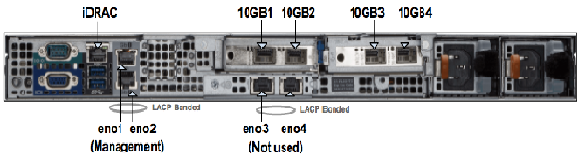
In the above figure in “Interfaces” section shows the rear view of the appliance and ethernet ports (10GB1/2/3/4) the CloudEOS and vEOS launcher script references. The ethernet ports in the CloudEOS and vEOS Router are virtual ethernet ports connected to one of the 10GB1/2/3/4 ports. VLANs are configured on each interface when installing CloudEOS and vEOS. The VLAN tagging is done by the SRIOV NICs. Note, that the connected networking devices need to have the same VLANs configured on the trunk port.
The appliance are shipped with a version of CloudEOS and vEOS Router image which is found in /data/tools. If you want to install the latest CloudEOS and vEOS Router image download desired CloudEOS.qcow2 version from Arista.com to the appliance to another directory.
The CloudEOS and vEOS launcher is a python script named dca-200-veos-setup-vm.py which is found in /data/tools directory as shown.
Router# ./dca-200-veos-setup-vm.py --help
usage: dca-200-veos-setup-vm.py [-h] [-n VMNAME] [-m IMAGE] [-d]
[-i [INTERFACE [INTERFACE ...]]] [-s MEMORY]
[-c CORES] [-r [REMOVE [REMOVE ...]]] [-q]
Create/Remove VEOS instances
optional arguments:
-h, --helpshow this help message and exit
-n VMNAME, --name VMNAME
Name of the VEOS VM
-m IMAGE, --image IMAGE
Qcow2 image name to use for launching the VM
-d, --debug Print detailed debug info
-i [INTERFACE [INTERFACE ...]], --interface [INTERFACE [INTERFACE ...]]
Interfaces and optional vlans/mac. The interfaces must
be listed in guest interfaces order. The interfase can
be specified either in PCI address format (using lspci
command) Or 10GB1/2/3/4. For example: '-i
10GB1,vlan=10 10GB2 10GB3,vlan=40' or '-i
3b:10.2,vlan=50 3b:10.3,vlan=10 af:10.2 af:10.3'
-s MEMORY, --memory MEMORY
Memory in Gbytes to assign to VM. Default is 4 Gb
-c CORES, --cores CORES
Number of Cores to assign to VM. Default is 4 cores
-r [REMOVE [REMOVE ...]], --remove [REMOVE [REMOVE ...]]
Remove VMs
-q, --query Query info about configured VMs
Example
Below is an example of commands used to launch a vEOS VMs with core count of 4 (default), 4GB memory (default), and with 4 ethernet interfaces.
Router# ./dca-200-veos-setup-vm.py -n veos-router1 -m /tmp/CloudEOS.qcow2 -i 10GB2,vlan=50 10GB1,vlan=10 10GB3,vlan=100 af:10.0,vlan=200
Extracting info for existing VMs: ['']
Total count is: 20, reserved for hypervisor: 2, Total Available: 18
Used CPU count is 0, Free cores 18
intfList is: ['10GB2,vlan=50', '10GB1,vlan=10', '10GB3,vlan=100', 'af:10.0,vlan=200']
Used CPU count is 0, Free cores 18
Free core set on Node 0 : [2, 4, 6, 8, 10, 12, 14, 16, 18]
CPU core used are:[2, 4, 6, 8]
Using PCI interfaces for new VM veos-router1:
('veos-router1', 'et1') --> 10GB2 PCI address: 3b:10.0 vlan 50 mac None
('veos-router1', 'et2') --> 10GB1 PCI address: 3b:10.1 vlan 10 mac None
('veos-router1', 'et3') --> 10GB3 PCI address: af:10.1 vlan 100 mac None
('veos-router1', 'et4') --> 10GB4 PCI address: af:10.0 vlan 200 mac None
The following observations are from the above example:
If an error occurs while creating a new VM using vEOS launcher, then refer to the Troubleshooting section of the chapter for more information.
The dca-200-veos-setup-vm.py script is used to remove the running VMs. The example below shows how to remove two existing VMs.
Router# ./dca-200-veos-setup-vm.py -r veos-router1 veos-router2
Cleaning up VM:veos-router1
Cleaning up VM:veos-router2
Besides launching/removing functionality, dca-200-veos-setup-vm.py script also provides a query command to print the current status of the running VMs. The output includes
Below is an example output:
Router# ./dca-200-veos-setup-vm.py -q
Extracting info for existing VMs: ['veos-router1', 'veos-router2']
Total count is: 20, reserved for hypervisor: 2, Total Available: 18
Used CPU count is 8, Free cores 10
VM veos-router1 :
interfaces:
et1 --> 10GB2 PCI address: 3b:10.0 vlan 50 mac 52:54:00:d4:f4:46
et2 --> 10GB1 PCI address: 3b:10.1 vlan 10 mac 52:54:00:d8:a9:50
et3 --> 10GB3 PCI address: af:10.1 vlan 100 mac 52:54:00:0c:0a:15
et4 --> 10GB4 PCI address: af:10.0 vlan 200 mac 52:54:00:20:4a:67
CPU Core Mapping:
0 --> 2
1 --> 4
2 --> 6
3 --> 8
VM veos-router2 :
interfaces:
et1 --> 10GB4 PCI address: af:10.2 vlan 50 mac 52:54:00:bb:ab:f1
et2 --> 10GB3 PCI address: af:10.3 vlan 10 mac 52:54:00:58:f7:2b
CPU Core Mapping:
0 --> 10
1 --> 12
2 --> 14
3 --> 16
Available free cores:3 5 7 9 11 13 15 17 18 19
For virtual console access there are two options:
[root@cv ~]# ethtool -i 10GB1 | grep bus
bus-info: 0000:3b:00.1
[root@cv ~]# ethtool -i 10GB2 | grep bus
bus-info: 0000:3b:00.0
[root@cv ~]# ethtool -i 10GB3 | grep bus
bus-info: 0000:af:00.1
[root@cv ~]# ethtool -i 10GB4 | grep bus
bus-info: 0000:af:00.0
[root@cv ~]# lspci | grep Ethernet
04:00.0 Ethernet controller: Broadcom Inc. and subsidiaries NetXtreme BCM5720 Gigabit Ethernet PCIe
04:00.1 Ethernet controller: Broadcom Inc. and subsidiaries NetXtreme BCM5720 Gigabit Ethernet PCIe
3b:00.0 Ethernet controller: Intel Corporation Ethernet 10G 2P X520 Adapter (rev 01)⇐ 10GB2 PF
3b:00.1 Ethernet controller: Intel Corporation Ethernet 10G 2P X520 Adapter (rev 01)⇐ 10GB1 PF
3b:10.0 Ethernet controller: Intel Corporation 82599 Ethernet Controller Virtual Function (rev 01)⇐ 10GB2 VF
3b:10.1 Ethernet controller: Intel Corporation 82599 Ethernet Controller Virtual Function (rev 01)⇐ 10GB1 VF
3b:10.2 Ethernet controller: Intel Corporation 82599 Ethernet Controller Virtual Function (rev 01)
3b:10.3 Ethernet controller: Intel Corporation 82599 Ethernet Controller Virtual Function (rev 01)
...
3b:17.6 Ethernet controller: Intel Corporation 82599 Ethernet Controller Virtual Function (rev 01)
3b:17.7 Ethernet controller: Intel Corporation 82599 Ethernet Controller Virtual Function (rev 01)
5e:00.0 Ethernet controller: Broadcom Inc. and subsidiaries NetXtreme BCM5720 Gigabit Ethernet PCIe
5e:00.1 Ethernet controller: Broadcom Inc. and subsidiaries NetXtreme BCM5720 Gigabit Ethernet PCIe
af:00.0 Ethernet controller: Intel Corporation Ethernet 10G 2P X520 Adapter (rev 01)⇐ 10GB4 PF
af:00.1 Ethernet controller: Intel Corporation Ethernet 10G 2P X520 Adapter (rev 01)⇐ 10GB3 PF
af:10.0 Ethernet controller: Intel Corporation 82599 Ethernet Controller Virtual Function (rev 01)⇐ 10GB4 VF
af:10.1 Ethernet controller: Intel Corporation 82599 Ethernet Controller Virtual Function (rev 01)⇐ 10GB3 VF
af:10.2 Ethernet controller: Intel Corporation 82599 Ethernet Controller Virtual Function (rev 01)
af:10.3 Ethernet controller: Intel Corporation 82599 Ethernet Controller Virtual Function (rev 01)
...
af:17.6 Ethernet controller: Intel Corporation 82599 Ethernet Controller Virtual Function (rev 01)
af:17.7 Ethernet controller: Intel Corporation 82599 Ethernet Controller Virtual Function (rev 01)
[root@cv ~]# virsh nodedev-list | grep 3b_00_0 ⇐ PF PCI
pci_0000_3b_00_0
[root@cv ~]# virsh nodedev-dumpxml pci_0000_3b_00_0
<device>
<name>pci_0000_3b_00_0</name>
<path>/sys/devices/pci0000:3a/0000:3a:00.0/0000:3b:00.0</path>
<parent>pci_0000_3a_00_0</parent>
<driver>
<name>ixgbe</name>
</driver>
<capability type='pci'>
<domain>0</domain>
<bus>59</bus>
<slot>0</slot>
<function>0</function>
<product id='0x154d'>Ethernet 10G 2P X520 Adapter</product>
<vendor id='0x8086'>Intel Corporation</vendor>
<capability type='virt_functions' maxCount='63'>
<address domain='0x0000' bus='0x3b' slot='0x10' function='0x0'/> ⇐ VF PCI
<address domain='0x0000' bus='0x3b' slot='0x10' function='0x2'/>
<address domain='0x0000' bus='0x3b' slot='0x10' function='0x4'/>
<address domain='0x0000' bus='0x3b' slot='0x10' function='0x6'/>
<address domain='0x0000' bus='0x3b' slot='0x11' function='0x0'/>
<address domain='0x0000' bus='0x3b' slot='0x11' function='0x2'/>
<address domain='0x0000' bus='0x3b' slot='0x11' function='0x4'/>
<address domain='0x0000' bus='0x3b' slot='0x11' function='0x6'/>
<address domain='0x0000' bus='0x3b' slot='0x12' function='0x0'/>
<address domain='0x0000' bus='0x3b' slot='0x12' function='0x2'/>
<address domain='0x0000' bus='0x3b' slot='0x12' function='0x4'/>
<address domain='0x0000' bus='0x3b' slot='0x12' function='0x6'/>
<address domain='0x0000' bus='0x3b' slot='0x13' function='0x0'/>
<address domain='0x0000' bus='0x3b' slot='0x13' function='0x2'/>
<address domain='0x0000' bus='0x3b' slot='0x13' function='0x4'/>
<address domain='0x0000' bus='0x3b' slot='0x13' function='0x6'/>
<address domain='0x0000' bus='0x3b' slot='0x14' function='0x0'/>
<address domain='0x0000' bus='0x3b' slot='0x14' function='0x2'/>
<address domain='0x0000' bus='0x3b' slot='0x14' function='0x4'/>
<address domain='0x0000' bus='0x3b' slot='0x14' function='0x6'/>
<address domain='0x0000' bus='0x3b' slot='0x15' function='0x0'/>
<address domain='0x0000' bus='0x3b' slot='0x15' function='0x2'/>
<address domain='0x0000' bus='0x3b' slot='0x15' function='0x4'/>
<address domain='0x0000' bus='0x3b' slot='0x15' function='0x6'/>
<address domain='0x0000' bus='0x3b' slot='0x16' function='0x0'/>
<address domain='0x0000' bus='0x3b' slot='0x16' function='0x2'/>
<address domain='0x0000' bus='0x3b' slot='0x16' function='0x4'/>
<address domain='0x0000' bus='0x3b' slot='0x16' function='0x6'/>
<address domain='0x0000' bus='0x3b' slot='0x17' function='0x0'/>
<address domain='0x0000' bus='0x3b' slot='0x17' function='0x2'/>
<address domain='0x0000' bus='0x3b' slot='0x17' function='0x4'/>
<address domain='0x0000' bus='0x3b' slot='0x17' function='0x6'/>
</capability>
<iommuGroup number='30'>
<address domain='0x0000' bus='0x3b' slot='0x00' function='0x0'/>
</iommuGroup>
<numa node='0'/>
<pci-express>
<link validity='cap' port='0' speed='5' width='8'/>
<link validity='sta' speed='5' width='8'/>
</pci-express>
</capability>
</device>
CloudEOS and vEOS launcher script provides the below mechanisms helping with debugging:
[root@cv /data/tools]# ./dca-200-veos-setup-vm.py -n veos-router2 -m ./CloudEOS.qcow2 -i af:10.0,vlan=50 10GB3,vlan=10
Extracting info for existing VMs: ['veos-router1']
Total count is: 20, reserved for hypervisor: 2, Total Available: 18
Used CPU count is 4, Free cores 14
intfList is: ['af:10.0,vlan=50', '10GB3,vlan=10']
Error: Interface af:10.0 is already assigned to VM veos-router1
[root@cv /data/tools]# ./dca-200-veos-setup-vm.py -n veos-router5 -m ./CloudEOS.qcow2 -i 10GB4,vlan=20 10GB1,vlan=30
Extracting info for existing VMs: ['veos-router1', 'veos-router2', 'veos-router3', 'veos-router4']
Total count is: 20, reserved for hypervisor: 2, Total Available: 18
Used CPU count is 16, Free cores 2
intfList is: ['10GB4,vlan=20', '10GB1,vlan=30']
Free core set on Node 0 : [18]
Free core set on Node 1 : [19]
Not enough CPU cores available on any NUMA node to allocate 4 cores.
The above example shows when user tries to create a VM with 4 cores (by default), an error message points out there’s not enough CPU cores available on any NUMA. It also prints out current free cores on each NUMA node (core 18 on node0 and core 19 on node1). User may choose to reduce the number of cores for new instance or reprovision existing VMs to fit new VM in.
/data/imaging/dca-200-veos-test.sh checks things like hyperthreading, interface MTU and etc.
[root@cv /data/imaging]# ./dca-200-veos-test.sh
Device '10GB1' successfully disconnected.
Connection successfully activated (D-Bus active path: /org/freedesktop/NetworkManager/ActiveConnection/19)
Device '10GB2' successfully disconnected.
Connection successfully activated (D-Bus active path: /org/freedesktop/NetworkManager/ActiveConnection/20)
Device '10GB3' successfully disconnected.
Connection successfully activated (D-Bus active path: /org/freedesktop/NetworkManager/ActiveConnection/21)
Device '10GB4' successfully disconnected.
Connection successfully activated (D-Bus active path: /org/freedesktop/NetworkManager/ActiveConnection/22)
Appliance is correctly set for VEOS use
/data/imaging/dca-200-veos-test-nics.py creates 4 VMs and sends traffic among them to test NICs are setup properly for creating new VMs and sending traffic.
[root@cv /data/imaging]# ./dca-200-veos-test-nics.py -a -i /data/tools/CloudEOS.qcow2
Cleaning up VMs:['autoDut1']
Cleaning up VMs:['autoDut2']
Cleaning up VMs:['autoDut3']
Cleaning up VMs:['autoDut4']
Creating instance autoDut1
Creating instance autoDut2
Creating instance autoDut3
Creating instance autoDut4
Starting Traffic test on created VMs
Running Tests onautoDut1
Running Tests onautoDut2
Running Tests onautoDut3
Running Tests onautoDut4
All Tests finished Successfully
Cleaning up VMs:['autoDut1']
Cleaning up VMs:['autoDut2']
Cleaning up VMs:['autoDut3']
Cleaning up VMs:['autoDut4']
If there are error messages shown from the above two test scripts, user can run /data/imaging/dca-200-veos-setup.sh to re-setup the appliance. Note, The /data/imaging/dca-200-veos-setup.sh will reconfigure the interfaces and other parameters on the appliance and reboot the VMs, which may affect the running VMs to working properly and stop.
The appliance shipped should be in good condition, and quality checked stage, where setup and test scripts have already been run. So it is NOT recommended for customer to run /data/imaging/dca-200-veos-setup.sh without contacting Arista support.
The 10G ethernet ports are tested using the following Arista transceivers:
Arista CloudEOS is now supported on Google Cloud Platform (GCP), as well as other public and private clouds.
Arista CloudEOS is a cloud-grade and feature-rich virtual router for Google cloud. This software-only release of EOS software is supported on public clouds, as well as on customer premises equipment running Linux and VMware hypervisors. By bringing advanced network telemetry and secure IPSec VPN connectivity in a software-only package, CloudEOS provides a consistent, secure and universal approach to hybrid cloud networking for any virtualized cloud deployment.
This release of CloudEOS is available as a software subscription in Google Cloud Launcher following a BYOL and PAYG license model. For BYOL instance, a CloudEOS license activation key must be obtained separately from Arista, which unlocks the platform from a default performance limit of 10 Mbps, and enable the use of IPsec encrypted VPNs. For PAYG instance, the license will be installed by the system automatically so customers can start using all features including IPsec and uncapped throughput. For more information about licensing, please refer to Chatper 2 - License Management.
This section describes the use of custom-data during the initial deployment of the vEOS router instance, GCP provides an option to upload custom-data. The custom-data used passes in the configuration for multiple entities. Currently, GCP supports only the EOS configuration. This configuration is separated using start and end markers.
The administrator is allowed to upload vEOS router configuration using custom-data while launching a router instance through the portal as shown below. Note, the custom-data works only during the first boot.
Note, the following regarding the custom-data.
Entity |
Markers |
File Path |
---|---|---|
EOS CLI configuration file |
|
N/A |
EOS CLI configuration file Use: %FORCE_USER_DATA% will forcibly apply the Arista startup configs in the user custom data under the %EOS-STARTUP-CONFIG-START% and%EOS-STARTUP-CONFIG-END% ) even when it is not a first time boot of the instance. |
%FORCE_USER_DATA% |
N/A |
Configuring custome-data for GCP instance through portal.