Taiwan RoHS Information
This appendix provides Taiwan RoHS information for switches covered by this guide.
For Taiwan BSMI RoHS Table, go to https://www.arista.com/assets/data/pdf/AristaBSMIRoHS.pdf.
This appendix provides Taiwan RoHS information for switches covered by this guide.
For Taiwan BSMI RoHS Table, go to https://www.arista.com/assets/data/pdf/AristaBSMIRoHS.pdf.
This appendix lists the Regulatory Model Numbers (RMNs), where applicable, for the product models for the switches described in this document.
| Regulatory Model Number (RMN) | Product Number(s) |
|---|---|
| AN1504 | DCS-7280SR-48C6 |
| AN1506 | DCS-7280TR-48C6 |
| AN1508 | DCS-7280QR-C36 |
| AN1604 | DCS-7280QRA-C36S |
| AN1608 | DCS-7280TRA-48C6 |
| AN1615 | DCS-7280SR2A-48YC6 |
| AN1623 | DCS-7280SRAM-48C6 |
| AN1701 | DCS-7280SR2K-48C6 |
| AN1626 | DCS-7280SRM-40CX2 |
| AN1708 | DCS-7280PR3-24, DCS-7280PR3K-24 |
| AN1730 | DCS-7280DR3-24, DCS-7280DR3K-24 |
| AN1715 | DCS-7280CR3-32P4, DCS-7280CR3K-32P4 |
| AN1731 | DCS-7280CR3-32D4, DCS-7280CR3K-32D4 |
| AN1728 | DCS-7280SR3-48YC8, DCS-7280SR3K-48YC8 |
| AN1742 | DCS-7280CR3-36S, DCS-7280CR3K-36S |
Review the following considerations when installing the device.
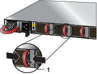
The following steps are required when removing power supplies from a switch.
_Numb.png)
| 1 | Release lever |
| 2 | Remove PSU |
You must make space for installing the power supply by removing an existing one Removing a Power Supply.
switch#show environment powerThe output of the command will list the power supplies in operation and should include the one you replaced.
The following steps are required when removing or replacing fans from a switch.
| 1 | Release lever |
You must make space for installing the fan module by removing an existing one.

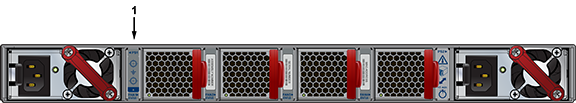
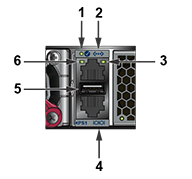
All switches covered by this guide use one of the rear panels shown below. Depending on the installed power supply module, the appearance could be different from those shown.

| 1 | Power supply 1 | 4 | Fan module 3 |
| 2 | Fan module 1 | 5 | Fan module 4 |
| 3 | Fan module 2 | 6 | Power supply 2 |

| 1 | Power supply module 1 | 6 | Fan module 3 | 11 | Fan module 3 status LED |
| 2 | System status LED | 7 | Fan module 4 | 12 | Fan module 2 status LED |
| 3 | Ethernet management port | 8 | Power supply module 2 | 13 | Fan module 1 status LED |
| 4 | Fan module 1 | 9 | Earth grounding pad | 14 | Console serial port |
| 5 | Fan module 2 | 10 | Fan module 4 status LED | 15 | USB port |

| 1 | Power supply module 1 | 5 | Fan module 1 status LED | 9 | Fan module 3 status LED |
| 2 | Power supply module 1 status LED | 6 | Fan module 2 release | 10 | Power supply module 2 |
| 3 | Management ports | 7 | Fan module 2 status LED | 11 | Power supply module 2 status LED |
| 4 | Fan module 1 release | 8 | Fan module 3 release | 12 | Fan module bezel1 |
1. Bezel color indicates airflow direction.
This appendix displays the front panel of all switches covered by this guide.

| 1 | Console port (serial) | 4 | Power supply 1 status LED | 7 | Ethernet Management port |
| 2 | System status LED | 5 | Power supply 2 status LED | 8 | Port numbers |
| 3 | Fan status LE | 6 | USB port |

| 1 | Console port (serial) | 4 | Power supply 1 status LED | 7 | Ethernet Management port |
| 2 | System status LED | 5 | Power supply 2 status LED | 8 | Port numbers |
| 3 | Fan status LED | 6 | USB port |

| 1 | Console port (serial) | 4 | Power supply 1 status LED | 7 | Ethernet Management port |
| 2 | System status LED | 5 | Power supply 2 status LED | 8 | Port numbers |
| 3 | Fan status LED | 6 | USB port |

| 1 | Console port (serial) | 4 | Power supply 1 status LED | 7 | Ethernet Management port |
| 2 | System status LED | 5 | Power supply 2 status LED | 8 | Port numbers |
| 3 | Fan status LED | 6 | USB port |

| 1 | System status LED | 3 | Power supply 1 status LED | 5 | USB port |
| 2 | Fan status LED | 4 | Power supply 2 status LED | 6 | Port numbers |

| 1 | System status LED | 3 | Power supply 1 status LED | 5 | USB port |
| 2 | Fan status LED | 4 | Power supply 2 status LED | 6 | Port numbers |

| 1 | System status LED | 3 | Power supply 1 status LED | 5 | USB port |
| 2 | Fan status LED | 4 | Power supply 2 status LED | 6 | Port numbers |

| 1 | System status LED | 3 | Power supply 1 status LED | 5 | USB port |
| 2 | Fan status LED | 4 | Power supply 2 status LED | 6 | Port numbers |

| 1 | System status LED | 3 | Power supply 1 status LED | 5 | USB port |
| 2 | Fan status LED | 4 | Power supply 2 status LED | 6 | Port numbers |

| 1 | System status LED | 3 | Power supply 1 status LED | 5 | USB port |
| 2 | Fan status LED | 4 | Power supply 2 status LED | 6 | Port numbers |

| 1 | System status LED | 3 | Power supply 1 status LED | 5 | USB port |
| 2 | Fan status LED | 4 | Power supply 2 status LED | 6 | Port numbers |
| 1 | System status LED | 3 | Power supply 1 status LED | 5 | USB port |
| 2 | Fan status LED | 4 | Power supply 2 status LED | 6 | Port numbers |

| 1 | System status LED | 3 | Power supply 1 status LED | 5 | Port numbers |
| 2 | Fan status LED | 4 | Power supply 2 status LED |

| 1 | Ethernet Management port | 4 | Power supply 1 status LED | 7 | Console port (serial) |
| 2 | System status LED | 5 | Power supply 2 status LED | 8 | Port numbers |
| 3 | Fan status LED | 6 | USB port |

| 1 | System status LED | 3 | Power supply 1 status LED | 5 | Port numbers |
| 2 | Fan status LED | 4 | Power supply 2 status LED | 6 | Port-speed group |

| 1 | System status LED | 3 | Power supply 1 status LED | 5 | Port numbers |
| 2 | Fan status LED | 4 | Power supply 2 status LED | 6 | Port-speed group |

| 1 | System status LED | 3 | Power supply 1 status LED | 5 | Port numbers |
| 2 | Fan status LED | 4 | Power supply 2 status LED | 6 | Port-speed group |

| 1 | System status LED | 3 | Power supply 1 status LED | 5 | Port numbers |
| 2 | Fan status LED | 4 | Power supply 2 status LED | 6 | Port-speed group |

| 1 | Port numbers | 3 | Fan status LED | 5 | Power supply 2 status LED |
| 2 | System status LED | 4 | Power supply 1 status LED | 6 | Port status LED (port 25) |
This appendix lists the installation parts contained in the switch accessory kit.
Each switch provides an accessory kit that contains parts that are required to install the switch.
Describes the rack mounting parts and cables requied for installation of the device.
Lists the parts required for a two-post and four-post mounting system.

| 1 | Two-post rack mount parts |
Lists the parts required for a two-post and four-post mounting system.

| 1 | Rail-slide |
| 2 | Rail-rod |
| 3 | Rack plugs (detail) |
| 4 | Rail (assembled) |
| Quantity | Description |
|---|---|
| 2 | Power cables: IEC-320/C13-C14, 13 A, 250 V |
| 1 | RJ-45 Patch Panel Cable |
| 1 | RJ-45 to DB9 Adapter Cable |

| SKU | Description |
|---|---|
| KIT-GND-EXT-1RU1 | Ground extender kit for NEBS compliance |
Reviews the Switch and Port Indicators of the device.
Front panel LEDs are located on the right side of the chassis and display system, fan, and power supply status.
The front panel LEDs are labeled either as in Figure 1 or as in Figure 2. Check your device for the specific method utilized.
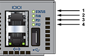
| 1 | System status LED | 3 | Power supply 1 status LED |
| 2 | Fan status LED | 4 | Power supply 2 status LED |
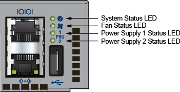
| 1 | System status LED | 3 | Power supply 1 status LED |
| 2 | Fan status LED | 4 | Power supply 2 status LED |
| LED Name | LED State | Device Status |
|---|---|---|
| System Status LED | Blinking Green | System is powering up. |
| Green | Normal operations. Due to power supply and fan redundancy, this LED will remain green if a single fan or power supply is missing or in a failed state. | |
| Blue | The locater function is active. | |
| Amber | Two or more fans (any combination of fan modules or PSU fans) are disconnected or malfunctioning. The switch will automatically execute a “graceful shutdown” shortly. | |
| Fan Status LED | Green | All fan and power modules are operating normally. |
| Amber | Single fan module is removed or malfunctioning. It is also amber when a PSU is completely removed or has a stuck fan rotor. | |
| Red | Two or more fans (any combination of fan modules or PSU fans) are disconnected or malfunctioning. The switch will automatically execute a “graceful shutdown” shortly. | |
| PSU [1:2] Status LED | Green | PSU is functioning and fully operational. AC is present, Aux output is ON, and Main output is ON. |
| Off | PSU has been removed or is not operating properly due to AC cord being unplugged, its fan rotor being stuck, or an internal fault. |
Port LEDs, located in the vicinity of their corresponding ports, provide link and operational status.
the following figure displays the Port LED location on the DCS-7050QX-32S switch.
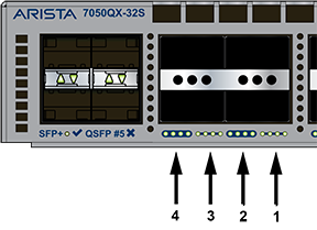
| 1 | Port 4 LEDs | 3 | Port 2 LEDs |
| 2 | Port 3 LEDs | 4 | Port 1 LEDs |
Table 2 provides status conditions that correspond to port LED states. Port LED behavior for QSFP+ and SFP+ ports is consistent.
| LED State | Status |
|---|---|
| Off | Port link is down. |
| Green | Port link is up. |
| Yellow | Port is software disabled. |
| Flashing Yellow | Port failed diagnostics. |
Fan and power supply modules are accessed from the rear panel.
Each fan and power supply module contains an LED that reports the module status.
Fan Status LEDs are on the fan modules, as displayed in Figure 4.
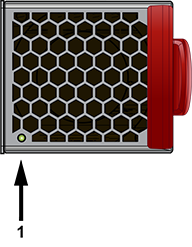
| 1 | Fan module status LED |
Table 3 provides status conditions that correspond to fan status LED states.
| LED State | Status |
|---|---|
| Off | The fan module is not detected. If it is inserted, it may not be seated properly. |
| Green | The fan is operating normally. This LED state is exclusive to its fan module, and independent of the states of its neighboring fans and power supplies. |
| Red | The fan has failed. |
The AC Power Supply Status LEDs are on the power supply modules, as displayed in Figure 5.
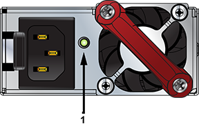
| 1 | Power supply status LED |
Table 4 provides status conditions that correspond to the AC power supply status LED states.
| Power Supply State | PWR-500AC-F PWR-500AC-R | PWR-745AC-F PWR-745AC-R | PWR-747AC-F PWR-747AC-R |
|---|---|---|---|
| Input power present Normal operation | Green | Green | Green |
| Input power present Power Supply fault | Yellow | Yellow | Yellow |
| No Input power Supply installed in chassis | Off | Off | Off |
| Input power present Supply not installed in chassis | Green | Green | Green |
The DC Power Supply Status LEDs are on the power supply modules, as displayed in Figure 6.
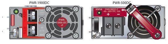
Table 5 provides status conditions that correspond to the DC power supply status LED states.
| Power Supply State | PWR-500DC-F PWR-500DC-R | PWR-1900DC |
|---|---|---|
| Input power present Normal operation | Green | Green |
| Input power present Power Supply fault | Blinking Yellow | Blinking Yellow |
| No Input power Supply installed in chassis | Off | Off |
| Input power present Supply not installed in chassis | Blinking Yellow | Blinking Yellow |
Arista switches ship from the factory in Zero Touch Provisioning (ZTP) mode. ZTP configures the switch without user intervention by downloading a startup configuration file or a boot script from a location specified by a DHCP server.
To manually configure a switch, ZTP is bypassed. The initial configuration provides one username (admin) accessible only through the console port because it has no password.
When bypassing ZTP, initial switch access requires logging in as admin, with no password, through the console port. Then you can configure an admin password and other password protected usernames.
This manual configuration procedure cancels ZTP mode, logs into the switch, assigns a password to admin, assigns an IP address to the management port, and defines a default route to a network gateway.
The device is in Zero Touch Provisioning mode and is attempting to
download the startup-config from a remote system. The device will not
be fully functional until either a valid startup-config is downloaded
from a remote system or Zero Touch Provisioning is cancelled. To cancel
Zero Touch Provisioning, login as admin and type 'zerotouch cancel'
at the CLI.
localhost login:localhost login:adminlocalhost>zerotouch cancelArista EOS
localhost login:admin
Last login: Fri Mar 15 13:17:13 on consolelocalhost>enable
localhost#configlocalhost(config)#username admin secret pxq123localhost(config)#ip route 0.0.0.0/0 192.0.2.1localhost(config)#interface management 1localhost(config-if-Ma1/1)#ip address 192.0.2.8/24
localhost#copy running-config startup-configWhen the management port IP address is configured, use this command to access the switch from a host, using the address configured in step 9.
ssh admin@192.0.2.8Refer to the Arista Networks User Manual for complete switch configuration information.
After mounting the switch into the rack, connect the switch to the data center ground.
Figure 1 displays the location of the grounding pads located on the bottom corners of the rear panel for the models that have no management ports on the rear panel. Figure 2 displays the location of the grounding pads on the rear panel for models that have management ports on the rear panel. There are threaded holes under the sticker on the right (next to PS2) that warns about “1 min”.Figure 3 displays the location of the grounding assembly on the rear panel for DCS-7280CR3-32P4.
À la terre et de mise à la terre fils cosses (M4 x 0.7) ne sont pas fournis. Calibre des fils doit satisfaire des exigences de l’installation locale et nationale. Disponible dans le commerce 6 fils AWG est recommandé pour les installations aux États-Unis.
| 1 | Earth grounding pads |

| 1 | Earth grounding pads |
The following steps assemble and attach a grounding assembly to the chassis before mounting it into the rack.
| Switch | Grounding Kit Adapter |
|---|---|
| 7280PR3-24 | KIT-GND-EXT-1RU |
| 7280PR3K-24 | KIT-GND-EXT-1RU |
| 7280DR3-24 | KIT-GND-EXT-1RU |
| 7280DR3K-24 | KIT-GND-EXT-1RU |
| 7280CR3-32P4 | KIT-GND-EXT-1RU |
| 7280CR3K-32P4 | KIT-GND-EXT-1RU |
| 7280CR3MK-32P4 | KIT-GND-EXT-1RU |
| 7280DR3-32P4 | KIT-GND-EXT-1RU |
| 7280DR3K-32P4 | KIT-GND-EXT-1RU |
Figure 4 shows the exploded and assembled views.

Power cords are optional and must be ordered separately. You must use an approved power cord compliant with local and national electrical codes or order one from Arista for use with the device.
Installation de cet équipement doit être conformes aux codes électriques locaux et nationaux. Si nécessaire, consulter les organismes de réglementation appropriés et des autorités de contrôle pour assurer la conformité.
The switch operates with two installed power supplies. At least one power supply must connect to a power source. Two circuits provide redundancy protection. Rear Panel displays the location of the power supplies on the rear panel of the switch.
Cet équipement doit être mis à la terre. Ne jamais modifier le conducteur de terre.
Cet appareil requiert une protection contre les surintensités.
The following AC power supplies are supported.
| PWR-500AC | PWR-745AC | PWR-1011-AC |
| PWR-511-AC | PWR-747AC | PWR-1511-AC |
Figure 5 displays an AC power supply, including the power socket on the left side of the module. The AC power supply connects to a circuit that provides the required power, as specified by Table 4.
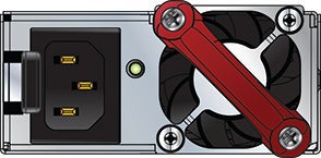
The power supplies require power cables that comply with IEC-320 and have a C14 connector. The accessory kit provides two IEC-320 C13 to C14 power cables.
The following DC power supplies are supported.
| PWR-500-DC | PWR-1900-DC | PWR-1511-DC |
| PWR-511-DC | PWR-1011-DC |
The following image displays examples of DC power supplies.

Un dispositif de sectionnement doit être fourni dans le cadre de l'installation.
Pouvoir assurer qu'il est retiré de circuits DC avant d'effectuer des actions d'installation . Localiser les disjoncteurs ou des fusibles sur les lignes de courant continu desservant les circuits. Coupez les circuits de lignes d'alimentation ou retirer les fusibles.
Le calibre du fil doit être conforme aux exigences locales et nationales et les codes électriques. Utiliser du fil de cuivre.
Appliquer connexion à la terre à l'interrupteur premier lors de l'installation et de supprimer la dernière alimentation lors du débranchement.
Before performing any installation actions, ensure power is removed from DC circuits by turning off the power line servicing the circuits. Prepare the stranded wiring before you begin a DC power installation.
| PSU | Wire Size(1) | Lug Type(2) | Tightening Torque | ||
|---|---|---|---|---|---|
| (AWG) | (mm2) | N•m | in.•lbs. | ||
| PWR-500-DC | 14 or larger | 2.0 or larger | ring or spade/fork | 1.0 | 9 |
| PWR-511-DC | 12 - 14 | 4.0 - 2.5 | 1.0 | 9 | |
| PWR-1900-DC | 4 - 6 | 21.2 - 13.3 | 2.7 | 24 | |
| PWR-1011-DC | 6 - 8 | 16.0 - 10.0 | 2.7 | 24 | |
| PWR-1511-DC | 4 - 6 | 25.0 - 16.0 | 2.7 | 24 | |
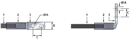
| 1 | Insulated wire | 3 | Lug | B | 1/2” |
| 2 | Heat-shrink tubing | A | 1/4” | C | 5/8” |
Figure 8 displays an example of connecting a PSU. To connect a DC power supply to a power source, perform the following:

Table 3 lists the pin connections of the RJ-45 to DB-9 adapter cable.
|
RJ-45 |
DB-9 |
RJ-45 |
DB-9 |
|||||
|---|---|---|---|---|---|---|---|---|
| RTS | 1 | 8 | CTS | GND | 5 | 5 | GND | |
| DTR | 2 | 6 | DSR | RXD | 6 | 3 | TXD | |
| TXD | 3 | 2 | RXD | DSR | 7 | 4 | DTR | |
| GND | 4 | 5 | GND | CTS | 8 | 7 | RTS | |
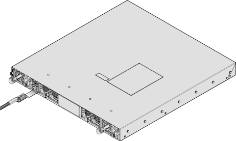
For most models, the front panel contains the console, management, and USB ports. The front panel ports display the ports on the front panel of the DCS-7050QX-32S switch. The rear panel ports display the ports on rear panel of the DCS-7280SR-48C6 switch. The front panel and rear panel display all switches covered by this guide.
| 1 | USB port | 3 | Console serial port |
| 2 | Ethernet management port |
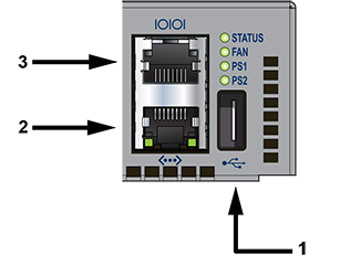
| 1 | System status LED | 3 | Activity status LED | 5 | USB port |
| 2 | Ethernet management port | 4 | Console serial port | 6 | Link status LED |
Flexion excessive peut endommager les câbles d’interface, notamment des câbles optiques.
Les procédure de montage du bâti est identique pour tous les commutateurs visés par ce guide. Illustrations dans ce chapitre montrent le montage d’un interrupteur de DCS-7050QX-32S.
After completing the instructions for your rack type, proceed to Cabling the Switch.
To mount the switch onto a two-post rack, assemble the mounting brackets to the chassis, then attach the brackets to the rack posts. Two-post accessory kits include the following two-post mounting parts.
2 Three-hole Mounting Brackets
Each chassis side has attachment pins that align with bracket holes. Pin orientation is symmetric and equidistant, supporting bracket placements where the flange is flush with the front switch panel, flush with the rear panel, or not flush with either panel. Each bracket hole includes a key-opening for placing the bracket flush with the chassis and then locking it into place.
Goupilles de fixation doivent être bloquer tous les trois trous de la bride supérieure.
The following figure displays the front bracket alignment for attaching the switch into a two-post rack.

The following figure displays improper bracket mounts for two-post rack mount.

The following procedure attaches the two-post rack mount brackets to the chassis.
The following figure shows the correct bracket attachment for a front mount.

| 1 | Step 1 | 4 | Bracket clip (attached) |
| 2 | Step 2 | 5 | Bracket clip (aligned) |
| 3 | Step 3 |
To remove the mounting bracket from the chassis, lift the front edge of the mounting bracket clip with a flathead screwdriver and slide the bracket away from the front flange (opposite from the installation direction).
This procedure attaches the switch to the rack.

After completing the two-post rack mount, proceed to Cabling the Switch.
The switch is mounted onto a four-post rack by assembling two rails onto the rear posts, sliding the switch onto the rails, then securing the switch to the front posts.
The rail-rods and rail-slides assemble into two identical slide-rails.
Each chassis side has attachment pins that align with bracket holes. Pin orientation is symmetric and equidistant, supporting bracket placements where the flange is flush with the front switch panel, flush with the rear panel, or not flush with either panel. Each bracket hole includes a key-opening for placing the bracket flush with the chassis and then locking it into place.
Goupilles de fixation doivent être lock au moins cinq des trous du six support.
The following figure displays proper bracket mount configuration examples for four-post mounting.

The following figure displays an improper bracket mount configuration example.


This procedure attaches mounting brackets to the switch chassis as depicted by the preceding figure.
To remove the mounting bracket from the chassis, lift the front edge of the mounting bracket clip with a flathead screwdriver and slide the bracket away from the front flange (opposite from the installation direction).
Rail-rods and rail-slides assemble into two identical rails. Each rail connects a front post to a rear post. When the rails are installed, the switch slides on the rails into the rack. Each bracket includes a screw that attaches the switch to the rail.
Each end of an assembled rail contains two rack plugs (Figure 8). The rails are installed into a rack by inserting the plugs into rack slots. When installing rails into posts with threaded or rounded holes, remove all plugs located on both sides of the assembled rails, then install the rails with bolts that fit the rack.

| 1 | Step 1 | 4 | Bracket clip (attached) |
| 2 | Step 2 | 5 | Bracket clip (aligned) |
| 3 | Step 3 |
This procedure attaches the rails to a four post rack:
The rail clip prevents the extension of the rail beyond the maximum supported distance between the front and rear rack posts.

| 1 | Rail-slide | 4 | Rail (assembled) |
| 2 | Rail-rod | ||
| 3 | Rack plugs |

| 1 | Inset A |
| 2 | Inset B |
After the rails are installed, the switch slides on the rails into the rack. Each bracket includes a thumb screw that attaches the switch to the rail.


After completing the four-post rack mount, proceed to Cabling the Switch.