EVPN Multicast vrf leaking
Overview
EVPN Multicast virtual routing and forwarding (vrf) leaking forwards multicast traffic from a sender in a tenant or external domain (vrf) to a different domain (vrf) with connected receivers. The source vrf refers to the vrf of the multicast sender, and the receiver vrf refers to the vrf of the multicast receiver.
Typically, a multicast receiver sends IGMP messages to a multicast stream, and a last hop router converts the IGMP message to a Protocol Independent Multicast (PIM) message and propagates them upstream on the network. When a vrf receives an IGMP or PIM message, a corresponding vrf leak occurs where the IGMP or PIM messages leak to the source vrf, which the source vrf processes. The corresponding EVPN Selective Multicast Ethernet Tag (SMET) route originates with the Supplementary Broadcast Domain (SBD) route target of the vrf and the route distinguisher (RD) where the sources connect. The receiver vrf RT and RD do not originate SMET routes.
When configuring EVPN Multicast vrf leaking, the source vrf contains the Multicase Outgoing interface (OIF) list of multicast routes from the receiver vrf. When the source vrf forwards traffic, the vrf sends a copy of the OIF list across the vrf.
EVPN Multicast vrf leaking supports a per multicast group configuration to leak multicast traffic.
In the following EVPN topology, two vrf tenants, red and blue, have multicase receivers and senders. The receiver, Rb1, on the blue vrf looks for group G on vrf, red, which has the resources. To enable the feature, configure vrf leaking for group G on the PE connected to the Rb1 with vrf red as the source vrf.
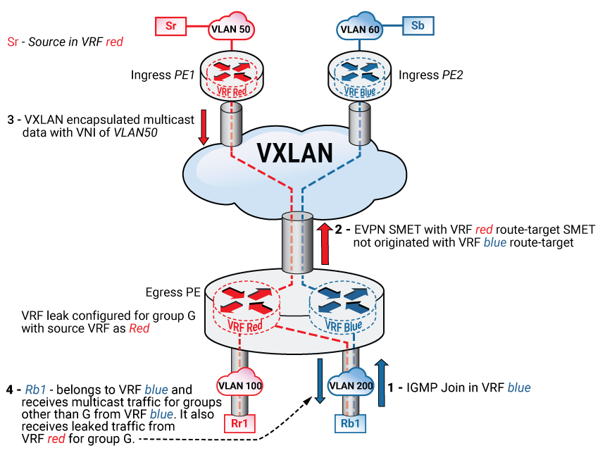
- Rb1 sends an IGMP join request for (*,G), and the host device is unaware of vrf leaking.
- vrf blue has the configuration for vrf leaking for G, so the egress Provider Edge (PE) router sends a SMET to the red vrf, and does not send a SMET to the blue vrf or the VLAN100.
- The ingress PE connected to the source on vrf red, sends VXLAN-encapsulated multicast packets with the VNI of the source VLAN across the EVPN core.
- The egress PE receives the VXLAN packet, decapsulates it, and routes the data packet to vrf blue.
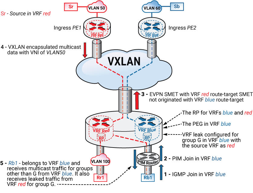
EVPN Multicast vrf leaking with a PIM EVPN Gateway (PEG)
On an EVPN network with a PEG role, the PEG acts as the rendezvous point (RP) for the leaked groups. The PEG also functions as the Rendezvous Point (RP) of the source vrf, which follows the PIM network model, where the PEG acts as the RP of the source and receiver vrfs. The configuration requires synchronization using a protocol such as Multicast Source Discovery Protocol (MSDP), and the source synchronization may be necessary with the source and receiver vrfs.
If an RP exists in the external PIM domain, then Multicast vrf leaking can be configured on that RP instead of the PEG, but this requires that both the source and receiver vrfs extend into the PIM domain that includes the RP.
In this case, the sources on the EVPN tenant vrfs exist in a different vrf from the RP, and the unicast route leaks to the source from the tenant vrf into the external domain vrf to build the multicast trees and perform Reverse Path Forwarding (RPF) validation.
Using MLAG as a PEG on an EVPN Network
When configuring vrf leaking on MLAG devices used as PEGS, configure the MLAG devices as a PEG in both the receiver vrf and the source vrf. Typically, the external PIM domain connects to the receiver. To enable PEG functionality on the source vrf, configure a stub VLAN and a corresponding SVI on both MLAG peers. Enable PIM on the SVIs of both peers and attach them to the source vrf. This enables PEG functionality in the source vrf as well.