This chapter describes the DMF Service Nodes available from Arista Networks.
DMF Service Node (DCA-DM-SC/DCA-DM-SC2) Specification
This section describes the LEDs for monitoring environmental and port status on the DMF Service Node (DCA-DM-SC 960GB and1.2TB, DCA-DM-SC2, 960GB, currently shipped appliances will have 960GB SSD).
The DMF Service Node (DCA-DM-SC/DCA-DM-SC2) is an enterprise-class, 2-socket, 1-RU rack-mounted hardware appliance designed to deliver the right combination of performance, redundancy, and value in a high-density chassis. It has 4 SNIs.
Figure 1. DMF Service Node (DCA-DM-SC/DCA-DM-SC2 with 960GB SSD) Bezel
1
Controller Node security bezel
2
LCD menu buttons
3
LCD panel
Figure 2. DMF Service Node (DCA-DM-SC/DCA-DM-SC2 with 960GB SSD) Front Panel
1
System identification button / indicator
5
Power-on indicator / Power button
2
Optical drive
6
Micro USB (not supported)
3
Video connector
7
Information tag
4
USB ports
8
Hard drive
Figure 3. DMF Service Node (DCA-DM-SC with 1.2TB HD) Bezel
1
Controller Node security bezel
2
LCD menu buttons
3
LCD panel
Figure 4. DMF Service Node (DCA-DM-SC with 1.2TB HD) Front Panel
1
System identification button / indicator
5
Power-on indicator / Power button
2
Optical drive
6
Micro USB (not supported)
3
Video connector
7
Information tag
4
USB ports
8
Hard drive
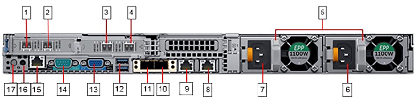
Figure 5. DMF Service Node (DCA-DM-SC/DCA-DM-SC2) Rear Panel
1
Ethernet connector 5 – 10GbE SFP+ Service interfaces SNI1
10
Ethernet connector 2 – Not supported
2
Ethernet connector 6 – 10GbE SFP+ Service interfaces SNI2
11
Ethernet connector 1 – Not supported
3
Ethernet connector 7 – 10GbE SFP+ Service interfaces SNI4
12
USB ports
4
Ethernet connector 8 – 10GbE SFP+ Service interfaces SNI3
13
Video connector
5
PSU status indicators
14
Serial connector (default baud rate 115200)
6
Power supply 2
15
iDRAC Ethernet interface
7
Power supply 1
16
System identification button
8
Ethernet connector 4 – Service Node management port 2 (10/100/1000Mb/s)
17
System identification indicator
9
Ethernet connector 3 – Service Node management port 1 (10/100/1000Mb/s)
DMF Service Node (DCA-DM-SDL/DCA-DM-SDL2) Specification
The DMF Service Node (DCA-DM-SDL/DCA-DM-SDL2) is an enterprise-class, 2-socket, 2RU rack-mount hardware appliance designed for high density, performance, redundancy, and value. It has 16 SNIs.
This section describes the LEDs for monitoring environmental and port status on the DMF Service Node (DCA-DM-SDL 960GB and 1.2TB, DCA-DM-SDL2 960GB. Currently shipped appliances will have 960GB SSD).
Figure 6. DMF Service Node (DCA-DM-SDL/DCA-DM-SDL2 with 960GB SSD) Bezel
1
System identification button / indicator
3
Power-on indicator / Power button
2
Service Node security bezel
4
USB ports
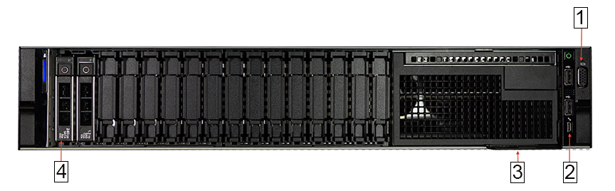
Figure 7. DMF Service Node (DCA-DM-SDL/DCA-DM-SDL2 with 960GB SSD) Front Panel
1
Front video connector
3
Information tag
2
Micro USB (not supported)
4
Hard drive
Figure 8. DMF Service Node (DCA-DM-SDL with 1.2TB HD) Bezel
1
System identification button / indicator
4
LCD panel
2
Service Node security bezel
5
Power-on indicator / Power button
3
LCD menu buttons
6
USB ports
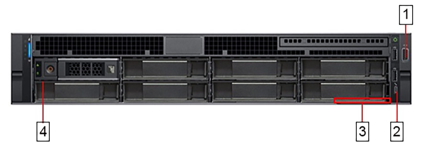
Figure 9. DMF Service Node (DCA-DM-SDL with 1.2TB HD) Front Panel
1
Front video connector
3
Information tag
2
Micro USB (not supported)
4
Hard drive
Figure 10. DMF Service Node (DCA-DM-SDL) Rear Panel
1
Service interfaces SNI8
16
Service interfaces SNI16
2
Service interfaces SNI7
17
Power supply 2
3
Service interfaces SNI6
18
PSU status indicator
4
Service interfaces SNI5
19
Power supply 1
5
Service interfaces SNI4
20
Ethernet connector 4 – Service Node management port 2 (10/100/1000Mb/s)
6
Service interfaces SNI3
21
Ethernet connector 3 – Service Node management port 1 (10/100/1000Mb/s)
7
Service interfaces SNI2
22
Ethernet connector 2 – Not supported
8
Service interfaces SNI1
23
Ethernet connector 1 – Not supported
9
Service interfaces SNI12
24
USB ports
10
Service interfaces SNI11
25
Rear video connector
11
Service interfaces SNI10
26
Serial connector (default baud rate 115200)
12
Service interfaces SNI9
27
iDRAC Ethernet interface
13
Service interfaces SNI13
28
System identification button
14
Service interfaces SNI14
29
System identification indicator
15
Service interfaces SNI15
Figure 11. DMF Service Node (DCA-DM-SDL2) Rear Panel
The following lists the meaning of the callouts in the rear panel.
1
Service interfaces SNI4
16
PSU status indicator
2
Service interfaces SNI3
17
Power supply 1
3
Service interfaces SNI8
18
Ethernet connector 4 – Service Node management port 2 (10/100/1000Mb/s)
4
Service interfaces SNI7
19
Ethernet connector 3 – Service Node management port 1 (10/100/1000Mb/s)
5
Service interfaces SNI2
20
Ethernet connector 2 – Not supported
6
Service interfaces SNI14
21
Ethernet connector 1 – Not supported
7
Service interfaces SNI13
22
USB ports
8
Service interfaces SNI10
23
Rear video connector
9
Service interfaces SNI9
24
Serial connector (default baud rate 115200)
10
Service interfaces SNI1
25
iDRAC Ethernet interface
11
Service interfaces SNI11
26
System identification button
12
Service interfaces SNI12
27
System identification indicator
13
Service interfaces SNI15
28
Service interfaces SNI5
14
Service interfaces SNI16
29
Service interfaces SNI6
15
Power supply 2
DMF Service Node (DCA-DM-SEL) Specification
This section describes the LEDs for monitoring environmental and port status on the DMF Service Node (DCA-DM-SEL 960GB and 1.2TB, currently shipped appliances will have 960GB SSD).
The DMF Service Node (DCA-DM-SEL) is an enterprise-class, 2-socket, 2RU rack-mount hardware appliance designed for high density, performance, redundancy, and value. It has 16 SNIs.
Figure 12. DMF Service Node (DCA-DM-SEL with 960GB SSD) Bezel
1
System identification button / indicator
3
Power-on indicator / Power button
2
Service Node security bezel
4
USB ports
Figure 13. DMF Service Node (DCA-DM-SEL with 960GB SSD) Front Panel
1
Front video connector
3
Information tag
2
Micro USB (not supported)
4
Hard drive
Figure 14. DMF Service Node (DCA-DM-SEL with 1.2TB HD) Bezel
1
System identification button / indicator
4
LCD panel
2
Service Node security bezel
5
Power-on indicator / Power button
3
LCD menu buttons
6
USB ports
Figure 15. DMF Service Node (DCA-DM-SEL with 1.2TB HD) Front Panel)
1
Front video connector
3
Micro USB (not supported)
2
Micro USB (not supported)
4
Hard drive
Figure 16. DMF Service Node (DCA-DM-SEL) Rear Panel
The following lists the meaning of the callouts in the rear panel.
1
Service interfaces SNI4
16
PSU status indicator
2
Service interfaces SNI3
17
Power supply 1
3
Service interfaces SNI8
18
Ethernet connector 4 – Service Node management port 2 (10/100/1000Mb/s)
4
Service interfaces SNI7
19
Ethernet connector 3 – Service Node management port 1 (10/100/1000Mb/s)