Cabling the Switch
Cabling the AC Power Supply
Grounding the Switch
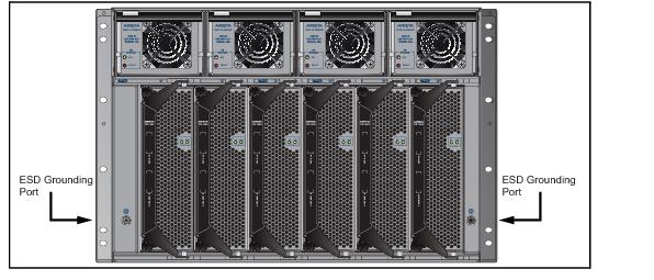
After mounting the switch into the rack, connect the switch to the data center ground. Figure 4-1 displays the location of the grounding pads located on both sides of the power input sockets.

Figure 4-1: Grounding Pad and ESD Grounding Port Sockets
After the switch is grounded, ESD wrist straps can be grounded by connecting them to one of the ESD grounding ports located between the power input sockets, (Figure 4-1) or the rear panel (Figure 4-2 depicts the location on the 7504). Receptacles are available in similar locations on other switch models.

Figure 4-2: ESD Grounding Port – Rear Panel
Connecting Power Cables to an AC Power Supply
Important! Installation of this equipment must comply with local and national electrical codes. If necessary, consult with the appropriate regulatory agencies and inspection authorities to ensure compliance.
Installation de cet équipement doit être conformes aux codes électriques locaux et nationaux. Si nécessaire, consulter les organismes de réglementation appropriés et des autorités de contrôle pour assurer la conformité.
Installation de cet équipement doit être conformes aux codes électriques locaux et nationaux. Si nécessaire, consulter les organismes de réglementation appropriés et des autorités de contrôle pour assurer la conformité.
The switch operates with four power supplies, each of which connects to circuits that provide 200-240 VAC, 50 or 60 Hz, and 20 A.
• DCS-7504 / 7504E requires the connection of one power supply to an active live circuit.
• DCS-7508 / 7508E requires the connection of at least two power supplies to active circuits.
Connecting power to all four power supplies protects against up to two failed power supplies and can provide grid-level redundancy. Energizing any power supply causes all power supply fans to function.
Figure 4-3 displays the power input sockets. Appendix C displays the front panel location of the sockets.

Figure 4-3: Power Input Sockets
Important! Read all installation instructions before connecting the system to the power source.
Lire toutes les instructions d’installation avant de brancher le système à la source d’alimentation.
Lire toutes les instructions d’installation avant de brancher le système à la source d’alimentation.
• Non-Redundant Configuration: Provide power to any two of the four power inputs.
• Redundant Power Supply Configuration: Provide power to all four power inputs.
• Power down the Switch: Remove all power cords from the power input sockets.
Each power supply includes a fan that maintains proper power supply temperature and cools the supervisor modules located below the power input sockets. The power supply fans are in addition to the fan modules located behind the power supplies. These appendices display the location of the following component on all switches described in this guide.
• Appendix C displays the front panel location of the power input sockets and supervisor modules.
• Appendix D displays the rear panel location of power supplies and fan modules.
The switch uses power cables that comply with IEC-320 and have a C19 plug. The accessory kit provides four IEC-320 C19 to C20 power cables, each two meters long.
To insert a power cable:
Step 1 Lift the retaining clip on each power input socket.
Step 2 Plug the power cables into the sockets.
Step 3 Adjust the retaining clips if needed for your power cords.
Step 4 Push the retaining clip back down over the cable.
Important! This equipment must be grounded. Never defeat the ground conductor.
Cet équipement doit être mis à la terre. Ne jamais modifier le conducteur de terre.
Cet équipement doit être mis à la terre. Ne jamais modifier le conducteur de terre.
Important! This unit requires overcurrent protection.
Cet appareil requiert une protection contre les surintensités.
Cet appareil requiert une protection contre les surintensités.
Connecting Supervisor Cables
Supervisor modules contain console, management, and USB ports. Figure 4-4 displays port locations on supervisors provided with 7508 / 7504 switches.

Figure 4-4: Supervisor Ports: 7508 / 7504 Switches
Figure 4-5 displays port locations on supervisors provided with 7508E / 7504E switches.

Figure 4-5: Supervisor Ports: 7508E / 7504E Switches
• Console (Serial) Port: Connect to a PC with RJ-45 to DB-9 serial adapter cable. Default switch settings include:
• 9600 baud
• No flow control
• 1 stop bit
• No parity bits
• 8 data bits
• Ethernet management port: Connect to 10/100/1000 management network with RJ-45 cable.
• USB Port: May be used for software or configuration updates.
Connecting Line Card Modules and Cables
Install required SFP, SFP+, and QSFP+ optic modules in line card module ports (Figure 4-6).

Figure 4-6: SFP or SFP+ ports
Connect cables as required to line card module ports or fixed MPO ports. Supervisor and line card module ejectors on the front of the chassis assist with cable management.
Caution Excessive bending can damage interface cables, especially optical cables.
Flexion excessive peut endommager les câbles d’interface, notamment des câbles optiques.
Flexion excessive peut endommager les câbles d’interface, notamment des câbles optiques.
