Installing and Configuring the DMF Recorder Node

This chapter describes the installation, initial configuration, and upgrade of the DMF Recorder Node.

frame-all

Overview

The DANZ Monitoring Fabric (DMF) Recorder Node (RN) is a traffic recording appliance with Arista Networks software running on Dell, Inc. servers.

The RN records packets from the network to disk and retrieves specific packets from disk quickly, efficiently, and at scale. It integrates with DMF for a single-pane-of-glass solution. A single DMF Controller can manage multiple RNs, delivering packets for recording through out-of-band policies. The Controller also provides centralized APIs for interacting with RNs to perform packet queries.

A DMF out-of-band policy directs the recording of matching packets to one or more RNs. The out-of-band policy defines the switch and port to attach the RN to the fabric. The policy treats these as “dynamic” delivery interfaces identified by unique names. The DMF Controller also provides commands for viewing errors, warnings, statistics, and the status of connected RNs.

The RN provides an OpenFlow agent that collects statistics and health information from the Controller. The OpenFlow agent also allows the Controller to configure the RN, eliminating the need to administer any RN directly during normal operation separately. To the DMF Controller, the OpenFlow agent causes the RN to appear as a special type of switch. Use the REST API to query the RN directly.

The DMF Recorder Node is based on the Dell server hardware and is available with the following interfaces:
  • Two management interfaces (10/100/1000 Mb/s)
  • One serial interface (DB-9)
  • One VGA interface
  • Two USB ports
  • One dedicated iDRAC port
Note: Arista recommends using an iDRAC connection to the DMF Controller, DMF Service Node, Arista Analytics Node, and DMF Recorder Node appliances. This connection helps with troubleshooting of issues. For more details, refer to the chapter on Using iDRAC later in this guide.
The following details the RN's storage capacity and the bandwidth provided by the data interfaces:
  • 192 TB packet storage capacity
  • 2 x 25 GbE SFP ports
  • 2 x 10 GbE copper ports
The following figure illustrates the bezel on the larger (HWA) DMF Recorder Node.
Figure 1. DMF Recorder Node (HWA) Front Panel


1 System identification button/indicator 4 LCD panel
2 Recorder Node Security Bezel 5 Power-on indicator / Power button
3 LCD menu buttons 6 USB ports
The following figure illustrates the front panel of the DMF Recorder Node.
Figure 2. DMF Recorder Node (HWA) Front Panel


1 Information Tag
2 Video connector
3 Micro USB (not supported)
4 Hard drives

The following figure illustrates the rear panel of the DMF Recorder Node.

Figure 3. DMF Recorder Node (HWA) Rear Panel
1 Ethernet connector 1 – Aux. Interface 9 Ethernet connector 4 – Recorder Node management. Backup, port 2 (10/100/1000 Mb/s)
2 Ethernet connector 2 – 25-GbE SFP+ Packet Recorder Interface 10 Ethernet connector 3 – Recorder Node management. Active, port 1 (10/100/1000 Mb/s)
3 SSD drives 11 USB ports
4 Power Supply 1 12 Video connector
5 Power Supply 2 13 Serial connector (Default Baud Rate 115200)
6 PSU status indicators 14 iDRAC Ethernet interface
7 Ethernet connector 6 – Not supported 15 System identification button
8 Ethernet connector 5 – Not supported 16 System identification indicator

DMF Recorder Installation Procedure

Prerequisite: To install the Recorder Node (RN) software on a Dell server, complete the following steps:
  1. Rack the RN Appliance.
    Note: The appliance interfaces are on the back of the device.
  2. Connect the RN management interface port 1 to the management network.
  3. Log in via the serial port or SSH using the admin account name. The baud rate is 115200.
  4. Insert a bootable USB drive in the RN USB port.
    Refer to Appendix Creating a USB Boot Image to make a bootable USB drive.
  5. Power cycle the appliance.
  6. Press F11 to select the Boot Manager to allow booting from USB.
    Figure 4. System Boot Manager Screen
  7. Select One-shot BIOS Boot Menu.
    The Boot Manager screen is displayed in the following figure.
    Figure 5. Boot Manager Main Menu
  8. Select the USB drive.
    Figure 6. Boot Menu
  9. Respond to the system prompt to login in using the admin account:
    recorder-node login: admin
    (Press Control-C at any time to cancel and start over)
    This product is governed by an End User License Agreement (EULA).
    You must accept this EULA to continue using this product.
    You can view this EULA from our website at:
    https://www.arista.com/en/eula
    Do you accept the EULA for this product? (Yes/No) [Yes] >
  10. Type Yes to accept the EULA, which is required to use the product. To view the EULA, type View, or refer to https://www.arista.com/en/eula.
    The system displays the following messages.
    Running system pre-check
    Finished system pre-check
    Starting first-time setup
  11. Configure the recovery password.
    Emergency recovery user password >
    Emergency recovery user password (retype to confirm) >
    Hostname > dmf-pr-740
  12. Configure IP addresses for the management network and DNS servers.
    [1] IPv4 only
    [2] IPv6 only
    [3] IPv4 and IPv6
    > 1
    IPv4 address [0.0.0.0/0] > 10.9.32.21/24
    IPv4 gateway (Optional) > 10.9.32.1
    DNS server 1 (Optional) > 10.3.0.4
    DNS server 2 (Optional) >
    DNS search domain (Optional) > qa.arista.com
    Administrator password >
    Administrator password (retype to confirm) >
    Controller address if deployment mode is preconfigured (L3 ZTN) (Optional) > 10.111.35.101
  13. If the RN is connected to the DMF Controller by a Layer 3 device (such as a router) in preconfigured (L3 ZTN) mode, enter the active DMF Controller's IP address.
  14. Configure the administrator password.
    Administrator password >
    Administrator password (retype to confirm) >
  15. Configure the NTP servers.
    -----------
    Default NTP servers:
    - 0.bigswitch.pool.ntp.org
    - 1.bigswitch.pool.ntp.org
    - 2.bigswitch.pool.ntp.org
    - 3.bigswitch.pool.ntp.org
    NTP server options:
    [1] Use default NTP servers
    [2] Use custom NTP servers
    [1] > 1
  16. Confirm the settings.
    Please choose an option:
    [ 1] Apply settings
    [ 2] Reset and start over
    [ 3] Update Recovery Password (*****)
    [ 4] Update Hostname (dmf-pr-740)
    [ 5] Update IP Option (IPv4 only)
    [ 6] Update IPv4 Address (10.9.32.21/24)
    [ 7] Update IPv4 Gateway (10.9.32.1)
    [ 8] Update DNS Server 1 (10.3.0.4)
    [ 9] Update DNS Server 2 (<none>)
    [10] Update DNS Search Domain (qa.arista.com)
    [11] Update Admin Password (*****)
    [12] Update NTP Option (Use default NTP servers)
    [1] >
    The system displays the following messages.
    [Stage 1] Initializing system
    [Stage 2] Configuring local node
    Waiting for network configuration
    IP address on bond0 is 10.9.32.21
    Generating cryptographic keys
    [Stage 3] Configuring system time
    Initializing the system time by polling the NTP servers:
    0.bigswitch.pool.ntp.org
    1.bigswitch.pool.ntp.org
    2.bigswitch.pool.ntp.org
    3.bigswitch.pool.ntp.org
    [Stage 4] Configuring cluster
    Cluster is already configured
    First-time setup is complete!
  17. Press Enter to complete the configuration.

Initial Configuration - GUI

After completing the installation, refer to the DANZ Monitoring Fabric User Guide to configure and operate the Recorder.

GUI Procedure

Complete the following steps to use the DANZ Monitoring Fabric (DMF) GUI to configure the Recorder Node (RN).
  1. Select Monitoring > Recorder Nodes from the main menu and click the Provision control (+) icon.
    Figure 7. Add Recorder Node
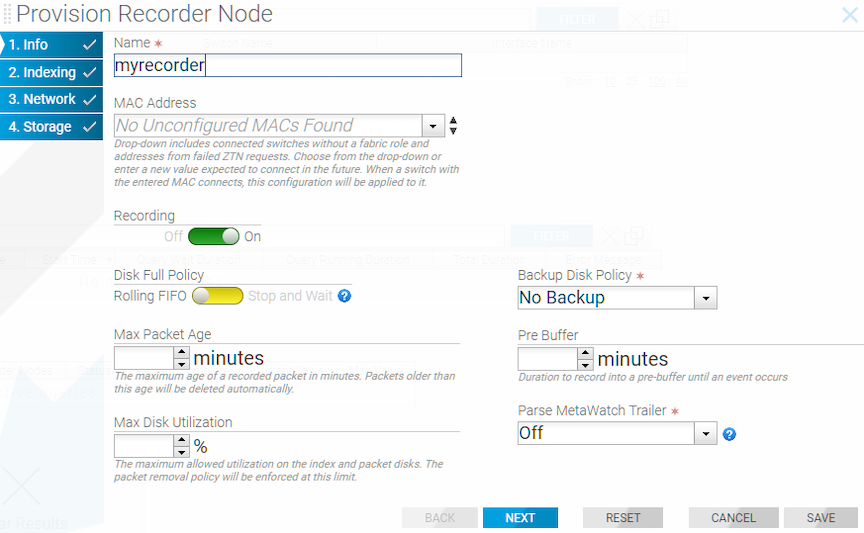
  2. Enter the required details by specifying a Name and identifying the MAC address of the RN appliance NIC connected to DMF.
    Tip: Choose the MAC address from the selection list if it has been discovered.
    Figure 8. Provision Recorder Node
  3. Click Save.
  4. Click the Provision control (+) at the top of the Interfaces section and enter the required information.
    Figure 9. Add Interface
    Figure 10. Provision Recorder Node
  5. Type an identifying Name (required) for the RN interface.
  6. Select the Switch and Interface to use to record the received traffic.
  7. Click Save.

Initial Configuration - CLI

CLI Procedure

To use the DMF CLI to perform the basic Recorder Node (RN) configuration, complete the following steps.

  1. Assign a name to the RN.
    (config)# recorder-node device bt-recorder3
  2. Set the MAC address of the RN.
    controller-1(config-recorder-node)# mac 18:66:da:fb:6d:b4
    If the management MAC is unknown, you can determine it from the chassis ID of connected devices using the show connected-devices command.
    Note: The following output is truncated and edited for documentation purposes.
    controller-1> show connected-devices
    # SwitchIF NameSPAN? Device NameDevice DescriptionChassis ID
    -|-----------|----------|-----|------------|-------------------|-----------------|
    1 filter-1ethernet1False localhostArista Networks EOS 2c:dd:e9:37:bf:47 
    2 delivery-2ethernet1False localhostArista Networks EOS 2c:dd:e9:37:bf:47 
    3 delivery-2ethernet43 False leaf1a 5c:16:c7:00:00:01 70:72:cf:c6:fe:f1 
    4 delivery-2ethernet48 False qa-ibm-1 IBM NOS 74:99:75:69:f7:00
    5 delivery-1ethernet1False leaf1a 5c:16:c7:00:00:01 70:72:cf:c6:fe:f1 
    6 delivery-1ethernet2False leaf1a 5c:16:c7:00:00:01 70:72:cf:c6:fe:f1 
    7 delivery-1ethernet3False leaf2a 5c:16:c7:00:00:01 70:72:cf:b5:e4:c0 
    8 delivery-1ethernet4False leaf2a 5c:16:c7:00:00:01 70:72:cf:b5:e4:c0
  3. Enable the RN.
    controller-1(config-recorder-node)# record
  4. Define the RN interface name.
    controller-1(config)# recorder-node device pr-intf-1
    controller-1(config-recorder-node)#
    Assign any alphanumeric identifier for the name of the RN interface, which changes the submode to config-bigtap-pkt-rec.
  5. Assign a switch and interface and optionally provide a text description.
    controller-1(config-recorder-node)# description 'Delivery point for recorder-node'
    controller-1(config-recorder-node)# recorder-node-interface switch
    00:00:70:72:cf:c7:cd:7d ethernet37
  6. Identify the RN interface by name in an Out-of-Band policy:
    controller-1(config)# policy pkt-rec
    controller-1(config-policy)# use-recorder-node pr-intf-1
  7. Configure the DMF policy to Identify the traffic to send to the RN.
    controller-1(config-policy)# 1 match any
    controller-1(config-policy)# filter-interface sw1-fil1
    The following example forwards all traffic received in the monitoring fabric on filter-interface sw1-fil1 to the RN interface.
    recorder-node pr-intf-1
    description 'Delivery point for recorder node'
    recorder-node-interface switch 00:00:70:72:cf:c7:cd:7d ethernet37
    
    policy pkt-rec
    action forward
    filter-interface sw1-fil1
    use-recorder-node pr-intf-1
    1 match any

Changing the Recorder Node Default Configuration

Configuration settings are automatically downloaded to the Recorder Node (RN) from the DANZ Monitoring Fabric (DMF) Controller, eliminating the need for box-by-box configuration. DMF supports overriding the default configuration for an RN from the config-recorder-node submode for any RN.
Note: Currently, these options are available only from the CLI and not in the DMF GUI.
To change the CLI mode to config-recorder-node, enter the following command from config mode on the active DMF Controller.
controller-1(config)# recorder-node device <instance>

Replace instance with the alias for the Recorder Node. This alias is associated with the MAC hardware address using the mac command.

Use any of the following commands from config-recorder-node submode to override the default configuration for the associated Recorder node.
  • banner: Set recorder-node pre-login banner message
  • mac: Configure MAC address for recorder-node name
Additionally, the following configurations can be overridden to use values specific to the recorder node or used in merge mode along with the configuration inherited from the Controller.
  • ntp: Configure packet-recorder to override default timezone and NTP parameters
  • snmp-server: Configure packet-recorder SNMP parameters and traps
  • logging: Enable packet-recorder logging to the Controller
  • tacacs: Set TACACS defaults, server IP address(es), timeouts and keys
To configure the recorder node to override the configuration inherited from the Controller, execute the following commands at the config-recorder-node submode:
  • ntp override-global: Override global time config with packet-recorder time config
  • snmp-server override-global: Override global SNMP config with packet-recorder SNMP config
  • snmp-server trap override-global: Override global SNMP trap config with packet-recorder SNMP trap config
  • logging override-global: Override global logging config with packet-recorder logging config
  • tacacs override-global: Override global TACACS+ config with packet-recorder TACACS+ config
To configure the recorder node to work in a merge mode by merging its specific configuration with that of the Controller, execute the following commands at the config-recorder-node submode:
  • ntp merge-global: Merge global time config with packet-recorder time config
  • snmp-server merge-global: Merge global SNMP config with packet-recorder SNMP config
  • snmp-server trap merge-global: Merge global SNMP trap config with packet-recorder SNMP trap config
  • logging merge-global: Merge global logging config with -packet-recorder logging config

The TACACS+ configuration does not provide a command usable with the merge option: it can be inherited from the Controller or overridden to use only the recorder node-specific configuration.