All switches this guide covers use one of the rear panels shown below. Depending on the installed power supply module, the appearance could differ from those shown. Some of the PSUs have a velcro strap for cable management.
Note: All devices are designed to fit into a 19” rack. The appearance may differ from those shown based on PSU and fan modules.
Note: Handle or bezel color indicates airflow direction.
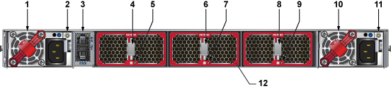
Figure 1. Rear Panel with Three Fan Modules and Management Ports (1RU)
1
Power Supply module 1
5
Fan module 1 status LED
9
Fan module 3 status LED
2
Power Supply module 1 status LED
6
Fan module 2 release
10
Power Supply module 2
3
Management ports
7
Fan module 2 status LED
11
Power Supply module 2 status LED
4
Fan module 1 release
8
Fan module 3 release
12
Fan module bezel
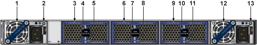
Figure 2. Rear Panel with Three Fan Modules (1RU)
1
Power Supply module 1
6
Fan module 2
11
Fan module 3 status LED
2
Power sSupply module 1 status LED
7
Fan module 2 release
12
Power Supply module 2
3
Fan module 1
8
Fan module 2 status LED
13
Power Supply module 2 status LED
4
Fan module 1 release
9
Fan module 3
5
Fan module 1 status LED
10
Fan module 3 release
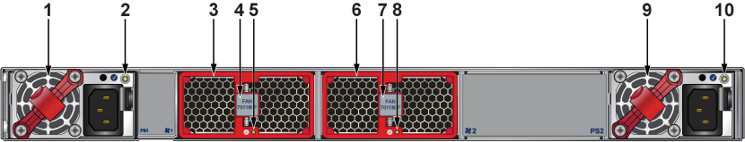
Figure 3. Rear Panel with Two Fan Modules (1RU)
1
Power Supply module 1
5
Fan module 1 status LED
9
Power Supply module 2
2
Power Supply module 1 status LED
6
Fan module 2
10
Power Supply module 2 status LED
3
Fan module 1
7
Fan module 2 release
4
Fan module 1 release
8
Fan module 2 status LED
Figure 4. Rear Panel with Ground Attach Point (2RU)
.png)