The most critical configuration in the NG Firewall is properly configuring your network settings in Config→Network.
For simple networks, the configuration completed during the Setup Wizard is sufficient. However, some networks have multiple WANs, multiple LANs, subnets, VLANs, VRRP, etc. This describes how networking operates and is configured in the NG Firewall.
The Interfaces page configures the network interfaces or the server.
Interfaces Grid
The Interfaces tab shows the current interfaces' status and configuration information.
Several columns along the top of the grid show the current interface status and configuration. Some are hidden by default.
Columns
Column
Description
Id
The ID is the unique integer primary key of the interface. All interface configurations will refer to It.
Name
This is the name/description of the interface. It is recommended that you choose names representative of their purpose.
Connected
This shows the device's current "connected" state, which is currently mapped to this interface. This may not display correctly for all network interface cards.
Device
This shows the current network device (physical NIC card or wireless card) mapped to this interface.
Config
This shows the current configuration for this interface. ADDRESSED, BRIDGED, or DISABLED.
Current Address
This shows the current address if one of the interfaces exists.
WAN
This shows true if the interface is configured as a WAN and false otherwise.
Edit
This column shows an edit button to edit the configuration of this interface.
Delete
This column shows a delete button on VLAN Tagged Interfaces to delete the interface. Physical interfaces cannot be deleted unless their physical devices have been removed from the system.
There are also several additional options on this page:
Remap Interfaces
This utility can change the mapping between physical devices and the corresponding interface configurations. This is useful if you want to use certain physical devices for certain purposes.
Refresh Device Status
This refreshes the "Connected" column in the interfaces grid. To verify your interface mapping, plug/unplug one network card at a time and select Refresh Device Status to verify that the expected interface changes the Connected status.
Add VLAN Tagged Interface
This allows for an additional 802.1q VLAN tagged interfaces. For more information, read the VLANs section in Network Configuration.
Interface Configuration
Clicking the Edit button on an interface will open the interface configuration settings.
An interface can be configured in many ways. Some settings and configuration options are only relevant and available in certain configurations. Based on an interface's configuration, certain options may appear and disappear. For example, when checking 'is WAN,' the options available to WAN interfaces will appear. After unchecking 'is WAN,' the WAN options will disappear, and the options for non-WAN interfaces will appear. Because of this, configuring your interface from the top of the page downward is suggested.
The table below shows the various configuration options and their meanings.
Interface Options
Option
Description
Interface Name
This is the name/description of the interface. It is recommended that you choose names representative of its purpose.
VLAN (802.1q) Interface
This is true if this is a tagged VLAN interface. Otherwise, this is not shown.
Parent Interface
This is the parent interface for this tagged VLAN interface. This is only shown for VLAN interfaces.
802.1q Tag
This is the VLAN tag for this interface. This is only shown for VLAN interfaces.
Wireless Interface
This is available if the interface is detected as a wireless (WLAN) interface. Otherwise, this is not shown.
Config Type
This is the basic configuration type of this interface. Addressed means this interface has its address and configuration. Bridged means this interface is bridged to another interface. Disabled means this interface is entirely disabled.
WAN Interface
This should be checked if this is a WAN (Wide Area Network) interface. This means it is connected to your ISP or an internet connection. It should be unchecked if this interface is connected to a private/local network.
Wireless Configuration - This section configures the wireless settings for wireless interfaces. It is only shown for wireless interfaces.
The encryption method is used to encode the wireless signal. WPA2 is recommended.
Password
When encryption is enabled, a password will be required to access the network.
Regulatory Country
Choose the country in which this NG Firewall is based. This is required to comply with regulations around Wi-Fi bands andfrequencies.
Channel
Choose from the available channels and 2.4GHz or 5GHz frequencies. The options available here depend on your wireless card.
Warning:Many chips/drivers do not correctly implement "Automatic" (ACS or Automatic Channel Survey), so depending on your card, it may not work.
Note:Automatic channel selection has been removed from modern builds due to a lack of support and usability issues.
IPv4 Options: This section configures this interface's Internet Protocol v4 (IPv4) settings.
Option
Description
Config Type
This is the IPv4 configuration type. Static means this interface has a static IPv4 address. Auto (DHCP) means this interface will automatically use DHCP to acquire an address. PPPoE means this interface will use PPPoE to acquire an address. This option is only available for WAN interfaces because non-WANs can only be statically configured.
Address
This is the IPv4 static address. It is only shown if the Config Type is Static.
Netmask
This is the IPv4 static netmask. It is only shown if the Config Type is Static.
Gateway
This is the IPv4 static gateway. It is only shown if the Config Type is Static.
Primary DNS
This is the primary DNS used for DNS resolution. It is only shown if Config Type is Static.
Secondary DNS
This is the secondary DNS used for DNS resolution. It is only shown if the Config Type is Static.
Address Override
If set, this address will be used instead of the one in the offered DHCP lease. It is only shown if Config Type is Auto (DHCP).
Netmask Override
If set, this netmask will be used instead of the one in the offered DHCP lease. It is only shown if Config Type is Auto (DHCP).
Gateway Override
If set, this gateway will be used instead of the one in the offered DHCP lease. It is only shown if Config Type is Auto (DHCP).
Primary DNS Override
If set, this will be used instead of the one in the offered DHCP lease. It is only shown if Config Type is Auto (DHCP).
Secondary DNS Override
If set, this will be used instead of the one in the offered DHCP lease. It is only shown if Config Type is Auto (DHCP).
Username
This is the PPPoE username. It is only shown in Config Type PPPoE.
Password
This is the PPPoE password. It is only shown in Config Type PPPoE.
Use Peer DNS
If checked, the server will use the DNS provided by the PPPoE server for DNS resolution. It is only shown in Config Type PPPoE.
Primary DNS
The primary DNS to be used for DNS resolution. It is only shown inthe Config Type PPPoE, and Use Peer DNS is unchecked.
Secondary DNS
The secondary DNS is to be used for DNS resolution. It is only shown in the Config Type PPPoE, and Use Peer DNS is unchecked.
IPv4 Aliases
This is a list of alias addresses. This is an additional list of addresses this interface will have and their associated netmasks.
IPv4 Options: NAT traffic exiting this interface (and bridged peers)
This option is only available on WAN Interfaces and defaults to checked. If checked, all traffic exiting this interface and interfaces bridged to it will be NATd, and all incoming sessions from this interface will be blocked unless they are forwarded via a Port Forward Rules or destined to the local server.
IPv4 Options: NAT traffic coming from this interface (and bridged peers)
This option is only available on non-WAN Interfaces and defaults to unchecked. If checked, all traffic from this interface and interfaces bridged to it will be NATd, and all incoming sessions to this interface will be blocked unless they are forwarded via a Port Forward Rules.
IPv6 Options: This section configures this interface's Internet Protocol v6 (IPv6) settings.
Option
Description
Config Type
This is the IPv6 configuration type. Disabled means the interface has no IPv6 configuration. Static means this interface has a static IPv6 address. Auto (SLAAC/RA) means this interface will use SLAAC to acquire an address automatically. This option is only available for WAN interfaces because non-WANs can only be statically configured.
Address
This is the IPv6 static address. Blank is allowed which means no IPv6 address will be given. It is only shown if the Config Type is Static.
Prefix
This is the IPv6 static prefix. It is only shown if the Config Type is Static.
Gateway
This is the IPv6 static gateway. It is only shown if the Config Type is Static.
Primary DNS
This is the primary DNS used for DNS resolution. It is only shown if the Config Type is Static.
Secondary DNS
This is the secondary DNS used for DNS resolution. It is only shown if the Config Type is Static.
IPv6 Aliases
This is a list of aliases addressed. This is an additional list of addresses this interface will have and their associated netmasks. This is only available on non-WAN interfaces.
IPv6 Options:Send Router Advertisements
If route advertisements are checked, they are sent on this interface. This is only available on non-WAN interfaces.
DHCP Configuration (server): Configures the DHCP serving options on this interface. DHCP Serving is only available on Addressed non-WAN interfaces.
Option
Description
Server
If selected, DHCP will be served to this interface so that machines can automatically acquire addresses.
Range Start
The start of the DHCP range.
Range end
The end of the DHCP range.
Lease duration
The duration of the provided DHCP leases in seconds.
Gateway Override
If set, this value will be provided as the gateway in the DHCP leases. Otherwise, this interface's static IPv4 address of this interface will be provided as the gateway.
Netmask Override
If set, this value will be provided as the netmask in the DHCP leases. Otherwise, this interface's static IPv4 netmask of this interface will be provided as the netmask.
DNS Override
If set, this value will be provided as the DNS in the DHCP leases. Otherwise, the static IPv4 address of this interface will be provided as the DNS. A single IPv4 address or a comma-separated list of IPv4 addresses is accepted.
DHCP Options
This is a list of DHCP options for dnsmasq. WARNING: This option is for advanced users. The specified DHCP options will be used on this interface. For example, to specify an NTP server, use enabled = true, description = "time server," and value = "42,192.168.1.2". For multiple DNS override servers, specify enabled = true, description = "DNS," and value = "6,192.168.1.1,192.168.1.2". The value must be specified in a valid dnsmasq format as described in the dnsmasq documentation.
DHCP Configuration (relay): This configures the DHCP relay on this interface.
Option
Description
Relay
If selected, DHCP requests received on this interface will be forwarded to a specified DHCP server.
Relay Host Address
The IP address of the relay host server.
Redundancy (VRRP) Configuration: This configures the VRRP redundancy options for this interface. VRRP is only available on statically assigned interfaces.
Option
Description
Enable VRRP
If checked, VRRP is enabled on this interface.
VRRP ID
The VRRP (group) ID of this server. It must match the VRRP ID of peers but must be unique on the server.
VRRP Priority
The VRRP Priority of this server. Higher value is a higher priority. (1-255)
VRRP Aliases
The list of VRRP Virtual Addresses. This list should be the same for all VRRP peers.
Interface Status
The status button on the interface brings up a window showing some of the statistics about the interface. This includes statistics, the ARP table, and the connected clients if it's a wireless interface.
Hostname
The tab configures the hostname and related settings of the NG Firewall server.
Hostname
Hostname
This is the name given to the NG Firewall server, such as "NGFW" or "firewall."
Domain
This is the domain name of the NG Firewall server. If your company uses "mycompany.com," you will likely want to use mycompany.com.
The Fully Qualified Domain Name (FQDN) for the NG Firewall server is Hostname + Domain. So Hostname = "NGFW" and Domain = "mycompany.com" means the FQDN for NG Firewall is ngfw.mycompany.com. If you have publicly available services like VPN and spam quarantines, you should ensure that ngfw.mycompany.com resolves in DNS to the/a public IP of the NG Firewall server.
Dynamic DNS Service Configuration
Several Dynamic DNS services are available to help those with dynamic public IPs. Some ISPs and areas only offer dynamic IPs, which can be problematic for networks with remote users who want to access services.
You can not remote users access the server/network by the public IP because it can change anytime.
These services exist to automatically update the public DNS entry when your DHCP address changes. This allows you to refer remote users to a FQDN such as "firewall.mycompany.com" and then automatically update the DNS resolution of "firewall.mycompany.com" to your public IP when it changes.
Enabled
If enabled, a Dynamic DNS server will be used to update the FQDN's DNS resolution.
Service
The drop-down shows the supported services. Choose the service you want to use.
Username
The username to use the service.
Password
The password for the service account.
Hostname(s)
The hostname will be updated with the NG Firewall's public IP address. Specify a single FQDN or multiple FQDNs separated by commas.
Services
The Services tab configures the local services available on the Arista Server. The Arista Server hosts an HTTPS and HTTP server (apache) that hosts services.
Services like administration, spam quarantine, reports, blockages, etc
HTTPS Port: TCP Traffic to the primary address of each interface on the HTTPS Port will be forwarded to the local webserver to provide services. Often, if you only have one public IP (1.2.3.4) and want to port forward the HTTPS port to an internal service like webmail to an internal machine, you will need to move the HTTPS Port to another port, like 4343, so that port can be forwarded to your internal machine. In this case, the administration and other HTTPS services will be accessible at https://1.2.3.4:4343/ , and 443 can be forwarded.
HTTP Port: TCP Traffic from non-WANs to the primary address of each non-WAN interface on the HTTP Port will be forwarded to the local web service to provide services. If those ports are required for port forwarding, the default HTTP Port can be changed to another port, like 8080.
Note:The configured HTTPS port will be forwarded to the local Apache process listening on port 443. The configured HTTP port will be forwarded to the local Apache process listening on port 80. The Access Rules will evaluate these sessions post-redirection where the destination port has already been altered.
Port Forward Rules
Port forwarding is a technique of rewriting the destination address and destination port of packets to send them to a new location.
Port Forward Rules
Port forwarding has many uses. The most common use is on networks doing NAT where internal servers have private addresses (i.e., 192.168.1.100); port forwarding allows traffic to the NG Firewall server's public IP to an internal host.
For example, suppose the email server is behind the NG Firewall with a private address (192.168.1.100), and the NG Firewall has one public IP (1.2.3.4), which all hosts are "sharing" via NAT to reach the internet. In that case, port forwarding can forward TCP traffic to 1.2.3.4, port 25 (SMTP) to 192.168.1.100, port 25.
Port Forwards Rules work like all rules in the NG Firewall, as described in the Rules documentation. Rules are evaluated in order on all new sessions. The destination is rewritten to the New Destination and the New Port of the first matching rule. If no rule matches, then no changes are made to the session.
Following the Port Forward Troubleshooting Guide is suggested if you are having issues with port forwards.
There are two types of port forward rules. To add a Simple Rule, click Add Simple Rule Click Add to add a regular rule, as described in the Rules documentation.
Simple Rules
Simple rules allow for most use cases and avoid extra configuration, which can lead to non-functional forwards. Simple port forward rules should be used wherever possible.
Enable Port Forward Rule
If checked, the rule is enabled. If unchecked, the rule has no effect and is disabled.
Description
A description of this rule. This is just for documentation.
Protocol
If "TCP," only TCP traffic to the specified port is forwarded. If "UDP," only UDP traffic to the specified port is forwarded. If "TCP and UDP," TCP and UDP traffic to the specified port is forwarded.
Port
This is a list of commonly forwarded ports. Use commas to separate multiple ports or a dash to denote a range. To specify an arbitrary port, select Other and specify the port.
New Destination
The new destination of the session after the port forward is typically the internal machine, such as 192.168.1.100.
Expert Rules
There are cases where a more complex rule is desired, such as:
forward non TCP/UDP protocols
Simple Rules can only forward TCP and UDP.
changing the new destination port
Simple Rules only rewrite the destination address. Expert rules are necessary if you also want to change the destination port. For example, forward TCP to 1.2.3.4 port 8080 to 192.168.1.100 port 80.
It is further limiting what traffic is forwarded.
Expert Rules allow additional conditions to limit when a port forward matches. For example, you can limit forwarded traffic to traffic from a specific interface, specific IP range, etc.
only to a certain public IP (not all NG Firewall IPs)
Simple Rules match all Destined Local traffic as described in Rules. If your NG Firewall has multiple public IPs and you only want to forward traffic to one of them, you can use Expert Rules.
Important: Simple rules are encouraged because users tend to misconfigure the port forward rule conditions. Adding MORE conditions means your port forward rule will match LESS traffic. For example, you might specify only forwarding traffic with "Source Interface = External" and then discover that traffic to a public IP from the internal interface is NOT forwarded because its source interface is NOT external.
Port forward rules:
Enable Port Forward Rules contain several components:
If checked, the rule is enabled. If unchecked, the rule has no effect and is disabled.
Description
A description of this rule. This is just for documentation.
Conditions
The conditions describing which sessions will match.
New Destination
The new destination of the session after the port forward. Typically, this is the internal machine, which is like 192.168.1.100.
New Port
Optional. If blank, the new destination port will remain unchanged. All matching sessions will be rewritten to the new destination port if specified.
Reservations
At the bottom of the Port Forward Rules tab is a list of reserved ports that can not be forwarded because they are currently used for NG Firewall services. These services can be moved to different ports in the Services tab if these ports are required for port forwarding.
NAT Rules
Network Address Translation (NAT) rules allow rewriting the source address of traffic.
Typically, NAT is used so machines on a private subnet (10.*.*.*, 192.168.*.*, etc.) can share a single public IP address. To do this, when a private machine (say 192.168.1.100) makes a connection to a public server (say google.com), the NG Firewall server rewrites the source address to the public IP address of NG Firewall (say 1.2.3.4) on the way out. When return traffic in that session returns to 1.2.3.4, it is rewritten back to the internal address, 192.168.1.100, and forwarded back to the internal server.
NAT
By default, "NAT traffic exiting this interface (and bridged peers)" is checked on Wide Area Network (WAN) Interfaces. This enables the NATing of all sessions exiting that WAN interface with the source address of the primary IP of that interface. In other words, all sessions leaving the External interface will use the External interface's primary IP.
Another option is "NAT traffic coming from this interface (and bridged peers)" on non-WAN Interfaces. If checked, all traffic coming from the interface will be NAT'ed using the primary IP address of its destination interface.
By default, since only "NAT traffic exiting this interface (and bridged peers)" is checked, NAT is only done on traffic that exits a WAN interface. This means traffic between internal networks will be un-NAT'ed, and each can reach the other using private addresses. If this is not desired, NAT can be done as traffic comes from a non-WAN by checking "NAT traffic coming from this interface (and bridged peers)." This means NAT occurs between local interfaces, and no traffic will flow between separate internal networks without explicit port forwards.
Note: Checking "NAT traffic exiting this interface (and bridged peers)" adds an implicit NAT rule to NAT all traffic exiting that interface to Auto. It also adds implicit Filter Rules to block all from that interface that is not to the local server and is not explicitly port forwarded.
Note: Checking "NAT traffic coming from this interface (and bridged peers)" adds an implicit NAT rule to NAT all traffic from that interface to Auto. It also adds implicit Filter Rules to block all to that interface that is not to the local server and is not explicitly port forwarded.
NAT Rules
Occasionally, additional rules are necessary for more complex NAT setups.
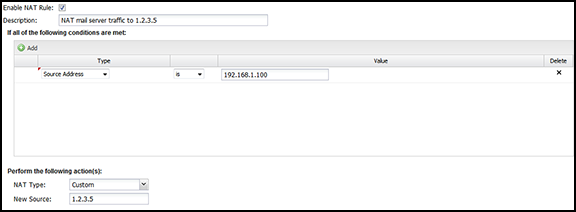
For example, let's assume you have two public IPs, 1.2.3.4 and 1.2.3.5. By default, you want all traffic to be NATd to the primary address 1.2.3.4, but you want your mail server (192.168.1.100) to send mail from 1.2.3.5. To do this, you need to add a NAT rule that says that traffic from the mail server should be NATd to 1.2.3.5. To do so, add a rule with Source Address = 192.168.1.100, where NAT Type = 'Custom' and New Source = '1.2.3.5'.
Another common scenario is setting up 1:1 NAT, using a paired Port Forward Rules and a NAT Rule.
A NAT rule
NAT Rules contain several components:
Enable
If checked, the rule is enabled. If unchecked, the rule has no effect and is disabled.
Description
A description of this rule. This is just for documentation.
Conditions
The conditions describing which sessions will match are documented in the Condition List of Rules documentation.
NAT Type
Auto or Custom. Auto means the session will be NAT'd to the primary address of the interface in which the session exits. Custom allows you to specify a specific IP.
New Source
If Custom is selected, specify the IP address to which the session will be NAT'd.
Like all Rules, the NAT rules are evaluated in order. The session will be NAT'd according to the first matching rule. If the rule does not match, the session will be NAT'd according to the checkboxes in the Interfaces settings. If no rules match and all NAT options in Interfaces are disabled or do not match the session in question, the session is not NATd and sent with the source address.
1:1 NAT
This section will help you set up 1:1 Network Address Translation (NAT)..
What is 1:1 NAT
1:1 Network Address Translation (NAT) is a mode of NAT that maps one internal address to one external address. For example, if a network has an internal servers at 192.168.1.10, 1:1 NAT can map 192.168.1.10 to 1.2.3.4, where 1.2.3.4 is an additional external IP address provided by your ISP.
How do I Setup 1:1 NAT?
You need to do three things:
Set up an external IP Address Alias.
Map inbound traffic destined for the external address so it is redirected to the correct internal machine.
Map outbound traffic from the internal machine to the correct external address.
In this example, we'll assume you're trying to set up 1:1 NAT for 192.168.1.10 to 1.2.3.4. You will need to be in advanced mode to configure 1:1 NAT.
Create an IP Address Alias on the WAN interface for 1.2.3.4, with the appropriate netmask provided by your ISP, and save it. This can be done at Config→Network→Interfaces on the specific interface and tells Arista to take ownership of that IP.
Create a port forward for inbound sessions and save it.This rule will forward all inbound sessions destined for 1.2.3.4 to 192.168.1.10: Destination Address: 1.2.3.4 New Destination: 192.168.1.10.
Create a port forward for inbound sessions and save it. This rule will forward all inbound sessions destined for 1.2.3.4 to 192.168.1.10: Destination Address: 1.2.3.4 New Destination: 192.168.1.10.
Create a NAT rule for outbound sessions—this causes all outbound sessions from 192.168.1.10 to be NATd to 1.2.3.4. This is done at Config→Network→NAT Rules: Source Address: 192.168.1.10 NAT Type: Custom New Source: 1.2.3.4 Once configured and saved, your 1:1 NAT setup is complete.
How do I Verify that 1:1 NAT is Working?
You can check outbound traffic by visiting your internal server and whatismyip.com and inbound traffic by testing your port forward. For example, if your internal server is running a web server, visit http://1.2.3.4/ from outside the network—it should load the web server on 192.168.1.10.
Bypass Rules
Bypass Rules work like other Rules. They are evaluated in order.
The NG Firewall's applications run in the "Arista VM" Arista Virtual Machine. UDP and TCP streams are endpointed during this process, and their streams are reconstructed in layer 7 (the application layer). The data stream then flows through the applications, and if passed eventually, the data is put back into new packets and sent on its way.
Unlike most proxy firewalls, NG Firewall processes almost all ports of both UDP and TCP at the application layer by default. Sometimes, it may be ideal to "bypass" traffic so that it is not subject to scanning. As shown in the image on the right, bypassed traffic will skip all the NG Firewall VM layer 7 processing and all the applications.
Sometimes, it is ideal to bypass traffic for performance reasons. This can be traffic you are not interested in scanning and want to save server resources or traffic extremely sensitive to scanning, like VoIP.
Sometimes, bypassing traffic that the application layer processing interferes with is also necessary.
As defined by your network configuration, bypassed sessions are routed, NATd, and filtered identically to all other sessions. The only difference is that bypassed sessions are not processed at Layer 7, so their traffic "bypasses" the applications.
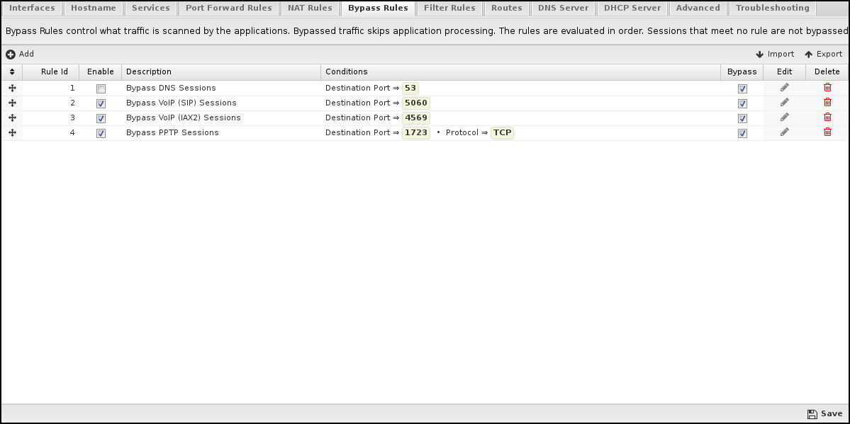
Bypass Rules
Bypass Rules work like other Rules. They are evaluated in order. The action from the first matching rule is taken.
For example, let's say you have a backup server at 1.2.3.4 and want to avoid scanning or interfering with traffic to that backup server. To bypass it, create a rule with Destination Address = 1.2.3.4 and action = "Bypass."
Bypass Rules contain several components:
Enable
If checked, the rule is enabled. If unchecked, the rule has no effect and is disabled.
Description
A description of this rule. This is just for documentation.
Conditions
The conditions describing which sessions will match are documented in the Condition list in the Rules section.
Action Bypass or Process. Bypass means the traffic will be bypassed. Process means the AVM and the apps will process the traffic.
Like all Rules, the Bypass rules are evaluated in order. The session will be processed or bypassed according to the first matching rule. If no bypass rule matches, the session will be processed.
Common Uses
There are several scenarios in which it makes sense to bypass traffic.
On large networks with servers that might be very busy, bypassing traffic that need not be scanned usually makes sense. This all depends on why you use the NG Firewall on your network.
Check- in Reports under "System" and look at the "Top Destination Ports." Occasionally, you'll see some bizarre port with millions of sessions, like Syslog. Often, these ports can be bypassed if you want to avoid scanning them.
Often, it makes sense to bypass port 53 from your internal DNS server so you can guarantee that NG Firewall will not interfere with your DNS server's resolution process. This is critical if the NG Firewall uses this server for DNS resolution.
If you are using NG Firewall for just Web Filter, you can bypass all of UDP and save lots of processing time; however, this is a bad idea if you are using Bandwidth Control, as then it would not be able to shape UDP.
Bypassing can sometimes be useful for troubleshooting. If you are having an issue with some traffic, you can bypass it to see if it helps. If it does help, then revert to processing and turn off the apps one at a time to see if one of the applications is interfering with the traffic in question.
Filter Rules
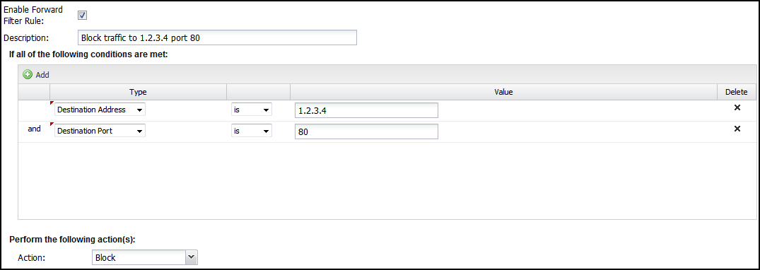
Filter rules are kernel-level iptables (Layer 3) "filter" rules. Filter rules apply to sessions transiting THROUGH the Arista server. By default, this ruleset is blank. Filter Rules are useful for blocking traffic going through the Arista server.
Filter Rules contain several components:
Enable Filter Rule
If checked, the rule is enabled. If unchecked, the rule has no effect and is disabled.
IPv6
If checked, the filter rule will also be active with IPv6 addressing.
Description
A description of this rule. This is just for documentation.
Conditions
The conditions describing which sessions will match. This is documented in the Condition_List section of Rules.
Action
Block or Pass. Block means the session dropped silently. Pass means the session will be passed.
As described in the Rules documentation, the rules are evaluated in order on all new sessions going through the Arista server. The action from the first matching rule is taken; if no rule matches, the session is passed. All passed sessions are still subject to processing in the Apps.
Why Use Filter Rules
The firewall app also offers block/pass rules. Several key differences determine whether using a filter rule rather than a firewall rule is appropriate.
Filter Rules still apply to bypassed traffic. The Firewall does not see bypassed traffic. This means if you want to block anything that's bypassed, you should use the Filter Rule.
Filter Rules apply to all protocols, while Firewall only sees TCP and UDP. If you want to block IP protocols other than TCP and UDP, you should use Filter Rules.
Firewall Rules have more application-layer conditions, such as Client exceeding Quota and HTTP: Client User OS. If you need these conditions, you should use the Firewall.
Firewall Rules are evaluated in the Firewall app and can be used in policies set up in Policy Manager.
Routes
Arista routes all traffic according to its routing table. As such, it is critical to configure your Arista server with a complete routing table.
If Arista does not have a complete routing table, it will not be able to reach hosts behind Arista, it will not properly route return traffic back to them, and they will be offline.
Figure 1. Network Routes Example
Routes contain several components:
Description: A description of this route. This is just for documentation.
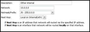
Network: This is the IP/network for this route. Upon saving, any bits past the prefix length or netmask will be zeroed out as they are irrelevant and are not accepted in a route.
Netmask/Prefix: This is this route's netmask (or prefix).
Next Hop:
This should either be a currently reachable local IP address or an interface chosen from the drop-down. If an IP address is specified, all traffic to this network will be routed to that IP address. If an interface is specified, all traffic to this network will be routed locally to that IP address using ARP to resolve those hosts.
Tip: It is easy to test routes using the Ping Test in Config > Network > Troubleshooting > Ping Test.
The route is likely correct if Arista can ping a host on the network in question. If Arista can ping a host on the network in question, the route probably needs to be corrected, and those hosts will not be online.
Common Uses
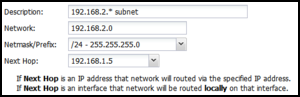
Some networks have subnets that exist behind other internal routers. For example, let's say my Internal interface is 192.168.1.1/24. A 192.168.2.0/24 network also exists behind another router at 192.168.1.5. Without this route, the entire network would be offline because its return traffic would go to the wrong place (the default gateway). In this case, I need to specify that the 192.168.2. The network is reachable through 192.168.1.5. This would look as follows:
Some networks also run multiple subnets on the same switch infrastructure internally. If these are "untagged" networks/VLANs, you must add a route. For example, let's say my Internal interface is 192.168.1.1/24. There is also a 10.0.0.0/8 network on this interface. These hosts would be offline without a route because their traffic would be routed to the wrong place (the default gateway). In this case, you must specify that 10.*.*.* hosts are directly reachable on the Internal interface. This would look as follows:
DNS Server
The DNS server settings configure the DNS server to run on the NG firewall.
These settings do NOT affect DNS traffic passing through the NG Firewall; only DNS traffic is sent to the NG Firewall server.
The DNS server on the NG Firewall is not required. However, it is often desired on small networks because the NG Firewall server caches DNS for the entire network. If the NG Firewall is configured 'as a router' to provide DHCP to clients on the internal network, the default is to provide the NG Firewall server as the DNS server.
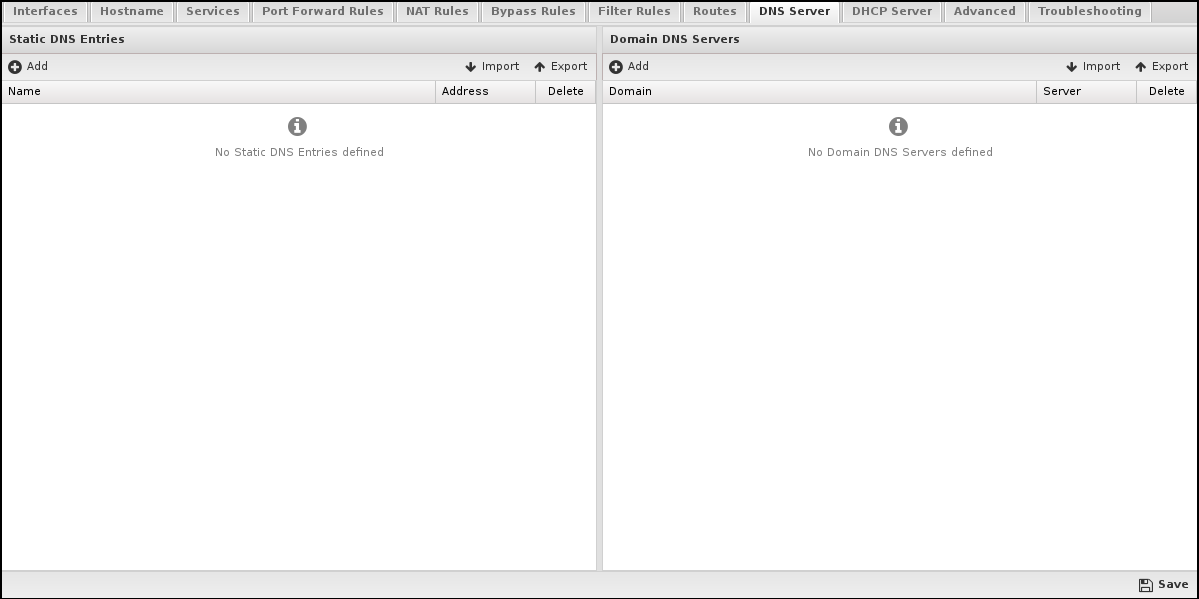
Static DNS Entries
Static DNS entries will always be resolved at the address provided. Often, this is useful for servers hosted internally. For example, if your mail server is local, you can add a static entry for mail.mycompany.com to its internal IP (like 192.168.1.20). This means machines using NG Firewall for DNS will resolve this hostname to the internal IP and communicate with it directly.
Domain DNS Servers
Often, certain domains need to be resolved using certain DNS servers instead of the DNS servers configured on the WAN interfaces. For example, you may want all queries to "*.mycompany.local" to go to the local DNS server for resolution. Domain DNS Servers allow you to specify that all queries matching the domain go to the specified server. For example, if all *.example.com queries should go to 192.168.1.20, then you can add an entry for Domain = example.com with Local Server = 192.168.1.20.
In this scenario, the NG Firewall and all those using the NG Firewall for DNS resolution will have the matching queries resolved through the specified server. For example, Suppose someone using the NG Firewall server for DNS resolves aaa.example.com. This DNS query will be forwarded to 192.168.1.20 instead of NG Firewall's upstream DNS servers configured in the WAN interface settings.
This can also tell NGFW how to do reverse DNS lookups using in-addr.arpa as the domain. For example, if you want 172.16.*.* reverse DNS queries to go to 192.168.1.10, then set the Domain of "16.172.in-addr.arpa" and the Local Server of "192.168.1.10". If you want for 10.*.*.*, reverse DNS queries to go to "1.2.3.4" and then set the Domain to "10.in-addr.arpa" and the Local Server of "1.2.3.4".
DHCP Server
These settings configured the settings of the DHCP Server running on the NG Firewall server.
DHCP Server
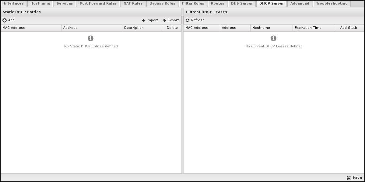
Note: The DHCP configuration for each interface is handled in the configuration of that interface in Config > Network > Interfaces. This page handles the global DHCP configuration.
Static DHCP Entries
This table contains any static DHCP leases. Entries in this table will always be given the same DHCP lease with the configured address. For example, if MAC Address = aa:bb:cc:00:11:22' and Address = 192.168.1.100, then when the machine with aa:bb:cc:00:11:22requests a DHCP lease, it will always be given 192.168.1.100.
Current DHCP Leases
This shows the current table of active DHCP leases and their expiration time.
Custom DNSMasq Options
This text field holds any custom DNSMasq options. This is for advanced users. Misconfiguration of this field will result in improper functioning of the NG Firewall server. Any text in this field will be appended to the dnsmasq.conf.
DNSMasq is the server the NG Firewall uses to provide DNS and DHCP services. DNSMasq documentation describes the options available.
Advanced
Options
Options contain some global networking options.
Enable SIP NAT Helper.
This enables the kernel SIP NAT fixup. Most SIP solutions handle NAT independently, but sometimes, the NAT device must rewrite the address inside the SIP. Enabling this will enable bypassed SIP sessions to be rewritten in the kernel. The default is off.
Send ICMP Redirects.
ICMP Redirects are used to alert machines if a shorter route is available. The default is on.
Enable Spanning Tree Protocol (STP) on Bridges.
This enables the Spanning Tree Protocol (STP) on bridges, a protocol used to help detect loops and avoid packet storms in this case. Given that a bridge loop is a fatal configuration, this option is off by default, so that the fatal configuration will fail quickly. It is NOT suggested that STP be relied on to stop bridge loops.
Strict ARP Mode
If enabled, ARP replies will only go out for network requests where the request source matches the expected configuration. This helps avoid ARP flux with complicated networks. Strict mode means arp_ignore = 1, arp_announce = 2. Loose mode means arp_ignore = 0, arp_announce = 0. More documentation about arp_ignore and arp_announce can be found here.
DHCP Authoritative
If enabled, all DHCP servings are authoritative. The default is on. DHCP Authoritative is documented here.
Block new sessions during network configuration.
If enabled when network setting changes are applied, all sessions will be blocked (dropped). This will provide increased security for router mode deployments and is not recommended for bridged mode deployments. The default setting is disabled.
Log bypassed sessions.
If enabled, bypassed sessions will be logged into the sessions table.
Log outbound local sessions.
If enabled, bypassed sessions created by the Arista server will be logged into the sessions table.
Log inbound local sessions.
If enabled, bypassed sessions to the Arista server will be logged to the sessions table.
Log blocked sessions.
All sessions blocked by filter rules or NAT or the shield will be logged to the sessions table if enabled.
QoS
About QoS
Quality of Service (QoS) is a mechanism to ensure high-quality performance to latency- and bandwidth-sensitive applications. It allows for the prioritization and differential treatment of traffic based on rules. Most often, this is used to improve the performance of latency and bandwidth-sensitive applications and traffic (like Voice over IP) at the cost of less important traffic such as peer-to-peer. QoS can greatly improve network traffic performance and important protocols, especially when the upload or download bandwidth is saturated. However, QoS is also detrimental to network performance if configured incorrectly. You are advised to read this section in its entirety before enabling QoS.
QoS settings can be found at Config→Network→Advanced→QoS.
The Seven Priorities
The seven priorities in the default configuration can be thought of as two sets - the top four priorities, Very High, High, Medium, and Low, all consume all available bandwidth if no higher priority class wishes to use it. Use these to prioritize traffic above normal, such as VoIP or important business traffic. The bottom three priorities, Limited, Limited More, and Limited Severely, are always limited regardless of other priorities' bandwidth consumption because their download and upload limits are set to less than 100%. These should be used in situations when the goal is to restrict traffic regardless of whether more bandwidth is available.
Examples
Below are a few examples going from simple to more complex:
The network is completely idle except for one Medium-priority download. This download uses all the available bandwidth and happens at full speed because no other priorities are using any traffic, and the Medium download limit is 100%.
The network is completely idle except for one low-priority download. This download uses all the available bandwidth and happens at full speed because no other priorities are using any traffic, and the Low download limit is 100%.
The network is completely idle except for one Limited More priority download. This download is given only half the available bandwidth because the reservation of Limited More is only 50%. The other 50% remains unused.
The network is fully saturated, and all seven priorities have several active downloads running. All Very High Priority downloads equally split 60% of the bandwidth (the Very High Reservation). All the other priorities similarly split their reservations down to Limited Severely, which splits the 1% reservation between all Limited Severely Sessions.
One medium-priority download and one Low-priority download run simultaneously. Because the other priorities are not using any of the reservations, the leftover is split relative to the Medium and Low reservations (5:12 or roughly 1:2.5). As such, the Medium priority download runs roughly 2.5 times faster than the Low priority download and together they consume all available bandwidth. (example: Low priority runs at 100kB/sec while the Medium runs at 250kB/sec and the total available bandwidth is 350kB/sec).
Two Limited Severe downloads are taking place simultaneously. All sessions are given the same priority and share the resources, so the two sessions split the priorities. Because all other priorities are not in use, the two split the bandwidth limit (10%), and each download runs at 5% of the total available bandwidth.
There are two WAN interfaces, and the WAN Balancer balances traffic across them. One medium-priority download occurs on WAN1, and one low-priority download occurs on WAN2. The medium-priority download is 100% of WAN1's bandwidth, and the low-priority download is 100% of WAN2's.
There are two WAN interfaces, and the WAN Balancer balances traffic across them. One medium-priority download occurs on WAN1, and one limited-priority download occurs on WAN2. The medium-priority download uses 100% of WAN1's bandwidth, and the limited-priority download uses 50% of WAN2's.
Attention:
Any given TCP download uses upload bandwidth to communicate to the sender that the data is being received. Usually, this upload bandwidth is only a little, but sometimes, if there is very little upload bandwidth available, it can be the limiting factor in the total rate of the download. The receiver can only communicate with the sender to tell it that data is being received sporadically, and as such, the sender will slow down. This is especially common with asymmetric links, especially if other uploads are in progress.
Because packets are often approximately 1500 bytes (the MTU size), the lower priorities must either send them or not. Splitting the packet and sending a portion is not an option. As such, the packet will be sent to prevent starvation but may sometimes exceed the 1% reservation. This is especially true on small links with very little bandwidth. As such, the granularity of the limits and reservations on small links may be skewed.
WANs are treated completely separately. Rules run on all traffic, regardless of which WAN the traffic is going out. However, the bandwidth settings on each WAN are separate, and they are treated as separate resources that are divided amongst traffic independently.
Settings
This section discusses the different settings and configuration options available for QoS.
Queue Discipline is the queueing discipline. The queue discipline is the algorithm used to "queue" packets ready to be transmitted. The default is Fair/Flow Queueing + Codel or fq_codel because it is the most modern, performant, and minimizes buffer bloat. Another commonly used and good algorithm is sfq or Stochastic Fairness Queueing (the old default). FIFO, or First in First out, is the simplest but could be more optimal as all packets are treated equally.
Enabled: Controls whether QoS is enabled or disabled. The default setting is unchecked, which means QoS is disabled, and no rules have any effect. WAN Bandwidth should be set before enabling QoS.
Default Priority: This priority is assigned to traffic that matches no QoS rule. You are advised to leave it at the Medium setting's default.
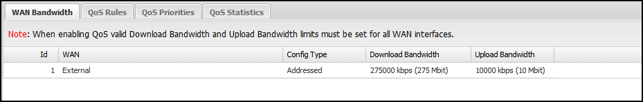
WAN Bandwidth: This is the most critical setting to configure correctly. It should be 85-95% of your line speed. We recommend contacting your ISP to get the proper numbers and testing to verify.
Finding the right settings for the WAN Bandwidth may take some experimentation. Quality of Service will only have an effect if the bandwidth limit is lowered. If the bandwidth setting is higher, traffic will be more manageable to a higher bandwidth. Remember, traffic only receives preferential treatment when the set bandwidth limit is saturated.
The QoS limits are configured correctly when the network has slightly less throughput than when QoS is disabled entirely. Depending on your hardware, the QoS settings may not match exactly the ISP-provided or testing Mbit numbers. Experimentation is required.
Figure 2. QoS - WAN Bandwidth
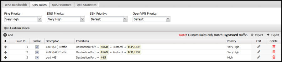
QoS Rules: Built-in rules to prioritize some typically important packets and traffic types. If you need more clarification, leave these as the default.
Figure 3. QoS Rules
QoS Custom Rules: This provides a simple way to create custom rules to prioritize or de-prioritize certain traffic.
As the note warns, QoS Custom Rules only match on bypassed traffic - they will do nothing if the traffic is not bypassed. If you want to prioritize scanned sessions, use Bandwidth Control. Default rules exist for VoIP traffic, which is also bypassed by default. Here's a list of the qualifiers you can use to build Custom QoS Rules:
QoS Priorities: This table allows customization of how each priority is treated and prioritized relative to other priorities. It is recommended that the default values be kept.
Figure 4. QoS Priorities
Download Limit can be any value between 1% to 100%. It limits the maximum amount of download bandwidth available to this priority under any circumstance.
Upload Limit can be any value between 1% to 100%. It. limits the maximum amount of upload bandwidth available to this priority under any circumstance.
Download Reservation can be any value between 1% and 100%. This value guarantees the minimum bandwidth available to this priority should it be needed under any circumstance.
Upload Reservation can be any value between 1% to 100%. It guarantees the minimum bandwidth available to this priority should it be needed.
Some bandwidth is always guaranteed (by the Reservation) to each priority. This prevents any priority from being fully starved and disconnected from the internet because higher priorities use all the bandwidth. When a higher class is not using its Reservation, the leftovers are reassigned to the lower classes based on the ratio of their reservations. For Example, by default, the Medium priority is limited to 100% of the download bandwidth and is guaranteed at least 12% of the download bandwidth.
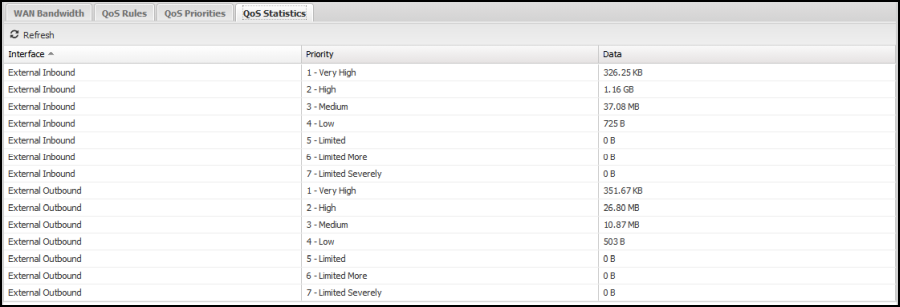
QoS Statistics is a status readout of recent activity. It is reset at reboot and when settings are saved.
It is useful for diagnosing which rules are being matched and assigning the proper priorities. It is also useful to test the total usage of each priority. The statistics are broken up by WAN interface. For Example, External-—Outbound shows the priority byte counts of all traffic going out the External WAN, while External—Inbound shows the priority byte counts of all traffic coming in the External WAN.
Figure 5. QoS Statistics
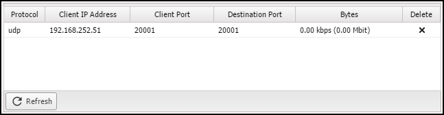
QoS Current Sessions shows a table of all active sessions and the assigned priority. This is useful for testing to ensure that priorities are being prioritized correctly. Please note that sessions are assigned priorities at creation time, so if rules are changed, active sessions will keep their current priority - only new sessions will be run against the new rules.
Access Rules
Access Filter rules apply to sessions destined to the Arista server's local processes and only sessions destined to the Arista server's local processes. These rules do not affect sessions passing through Arista and are only used to limit and secure access to local services on the Arista server.
Note: Improperly configuring access rules can compromise the security and proper functioning of the Arista server.
Note: Disabling rules in the default configuration may interfere with the proper functioning of many features of the Arista server.
There are two rules not enabled by default:
Allow HTTPS on WANs - enable this rule if you would like HTTPS access externally.
Allow SSH - enable this rule if you want SSH access to Arista's SSH service.
Note: Changing other settings of Access Rules is not recommended.
Access Rules Configuration
Enable Access Rule contain several components:
If checked, the rule is enabled. If unchecked, the rule has no effect and is disabled.
IPv6
If checked, the filter rule will also be active with IPv6 addressing.
Description
A description of this rule. This is just for documentation.
Conditions
The conditions describing which sessions will match.
Action
Block or Pass. Block means the session dropped silently. Pass means the session will be passed.
The rules are evaluated in order on all new sessions going to the Arista server as described in the Rules documentation. The action from the first matching rule is taken; if no rule matches, the session is passed.
Universal Plug and Play
About UPnP
Universal Plug and Play (UPnP) allows clients to create firewall port forward rules. Common uses include:
Allowing gaming consoles to host games.
Enables BitTorrent clients to host uploads.
You can find UPnP settings at Config > Network > Advanced > UPnP.
Security Considerations
These are considered "automatic port forward rules"; therefore, you should consider the potential security implications before enabling them in your environment. You probably want them enabled in a home environment with an Xbox, but you likely do not want them enabled in an office environment.
Settings
This section discusses the different settings and configuration options available for QoS.
Enabled: Controls whether UPnP is enabled or disabled. The default setting is unchecked, which means UPnP is disabled.
Secure Mode: is an option that restricts port creation to the client system. In most environments, you should leave this enabled.
UPnP Status is a status readout of recent activity. The statistics are reset at reboot and when settings are saved.
Access Control Rules
These rules allow you to control which networks can use UPnP and the ports they can manage, along with an allow or deny action. All rules are processed in order.
The default rules for Allow all and Deny all allow all UPnP traffic if UPnP is enabled.
To control access to a particular network, create a new Allow rule for that network and ports and ensure it is above the Deny all rule.
Network Cards
This grid configures the various options of the network cards in the Arista server.
MTU is the maximum transmission unit. The correct configuration is Auto, which is usually 1500. Occasionally, if the MTU is lower and PMTU (Path MTU discovery) is broken, it may be necessary to lower the MTU manually to a lower value. No settings (blank) are "Auto"—any other setting is an explicit hardcoded MTU.
The Ethernet Media drop-down configures the duplex of the Network card. Usually, Auto is the correct value. However, some network cards do not automatically configure the duplex setting properly or perform poorly when Auto is configured. In those cases, you can manually configure the speed and duplex settings.
DNS and DHCP
Custom Dnsmasq Options
This text field holds any custom Dnsmasq options. This is for advanced users. Misconfiguration of this field will result in improper functioning of the Arista server. Any text in this field will be appended to the dnsmasq. conf.
Dnsmasq is the server Arista uses to provide DNS and DHCP services. Dnsmasq documentation describes the options available.
Arista does not support any custom configurations for Dnsmasq.
Netflow
NetFlow is a feature developed by Cisco that can collect IP network traffic information as it enters or exits an interface. By analyzing the data provided by NetFlow, a network administrator can determine the source and destination of traffic, class of service, and the causes of congestion. A typical flow monitoring setup consists of three main components:
Flow exporter: aggregates packets into flows and exports flow records towards one or more flow collectors. In this case, the NGFW.
Flow collector: responsible for reception, storage, and pre-processing flow data from a flow exporter.
Analysis application: analyzes received flow data in the context of intrusion detection or traffic profiling, for example.
Netflow settings are located in Config→Network→Advanced→Netflow.
Netflow enabled
This enables the sending of Netflow data to the specified Netflow collector.
Host
The IP address or hostname of the NetFlow collector.
Port
The port for the Netflow collector.
Version
The version of NetFlow to send. NGFW supports multiple standard versions: v1, v5, and v9.
Dynamic Routing
About Dynamic Routing
Dynamic routing allows for exchanging routes between other routers using Border Gateway Protocol (BGP) and Open Shortest Path First (OSPF).
You can find Dynamic Routing settings at Config→Network→Advanced→Dynamic Routing.
BGP Overview
The Border Gateway Protocol (BGP) requires all nodes known as neighbors to be identified and added to the settings.
OSPF Overview
Open Shortest Path First (OSPF) does not require all nodes to be known. Instead, each route is associated with a group called an area. OSPF can be hierarchical in multiple areas, so some networks are publicly known, and others are private. Additionally, OSPF supports authentication.
Settings
This section reviews the different settings and configuration options available for Dynamic Routing.
Dynamic Routing Enabled: This controls whether dynamic Routing is enabled or disabled. The default setting is unchecked, which means dynamic Routing is disabled. BGP and OSPF must also be enabled.
Status: Overall status of dynamic routing shows:
Acquired Dynamic Routes: All routes obtained from enabled dynamic routing protocols.
BGP Status Information about each BGP neighbor, including messages received, sent, and uptime.
OSPF Status Information about discovered OSPF neighbors, such as their IP address and the time remaining until they next synchronize.
BGP: Enable BGP protocol.
Router ID: An IP-like identifier. It can be any IP-address-like value, but it is typically your WAN address.
Router Authentication Server: This system's Autonomous System (Authentication Server) number can be any number from 1 to 65535, but it must be unique to your BGP network.
Neighbors Define each BGP neighbor here. You will need to know each neighbor's IP address and Authentication Server.
Networks Define each local network route to share via BGP.
OSPF: Enable OSPF protocol.
Network Reports
Network reports can be accessed via the Reports tab at the top or the Reports tab within the settings. All pre-defined reports will be listed along with any custom reports that have been created.
Reports
Reports can be searched and further defined using the time selectors and the Conditions window at the bottom of the page. The data used in the report can be obtained using the Current Data window on the right.
Table 1. Pre-Defined Report Queries
Network Summary
A summary of network traffic.
Data Usage (by interface)
The total data usage by interface.
Data Usage per Day (by interface)
The data usage of each interface by day.
Data Rx-Usage (by interface)
The total received data usage by interface.
Data Tx-Usage (by interface)
The total received data usage by interface.
Sessions
The total number of scanned and bypassed sessions over time.
Sessions Per Minute
The total number of scanned and bypassed sessions created per minute.
Sessions Per Hour
The total, scanned, and bypassed sessions created per hour.
Bandwidth Usage
The approximate averaged data transfer rate (total, sent, received) over time.
Top Client Addresses
The number of sessions grouped by client (source) address.
Top Server Addresses
The number of sessions grouped by server (destination) address.
Top Server Ports
The number of sessions grouped by server (destination) port.
Top IP Protocols
The number of sessions grouped by IP protocol number.
Top Server Countries
The number of sessions grouped by server (destination) country.
Interface Usage
The RX rate of each interface over time.
Arista handles all Sessions
All sessions.
Scanned Sessions
All sessions that were not bypassed.
Bypassed Sessions
All sessions matching a bypass rule were bypassed.
The Connectivity Test checks that your NG Firewall can resolve and connect. This is an important test to establish that your WAN connections are functioning properly.
Ping Test
A simple Ping utility. Enter a hostname or IP and ping away.
DNS Test
A simple DNS utility. Enter a hostname and get an IP.
Connection Test
The Connection Test is a very useful tool for checking the status of a port on a remote machine. Enter an IP or Hostname and a Port, click Run Test, and see what happens.
Traceroute Test
A Simple Traceroute utility. Enter a hostname or IP and see what's between your NG Firewall and the remote machine.
Download Test
Provides a utility to test the download speed that NG Firewall has available. This download is not scanned to provide an upper bound of the bandwidth available to the NG Firewall as a single TCP download. Note that the results of this test are displayed in MBps, megabytes per second. You must multiply this result value by eight to get the speed test result in Mbps, megabits per second.
Packet Test
The Packet Test is a very powerful troubleshooting tool. Select an interface to listen to and a timeout value, then hit Run Test to see traffic on that interface. You can filter by IP and port to, for example, check if traffic is hitting an interface or if a remote machine is answering a request.