Heat Maps
Heat Maps are used to help the user to visualize the coverage, link speed and channels of placed devices on the floor plan.
Default View
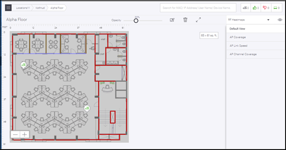
Default View shows the floor plan and placed devices on the floor.
- Select FLOOR PLANS tab from the left panel.
- Select the existing floor plan for which you wish to see the Default View.
- Choose RF Heatmaps option from the right hand side panel.
- Select Default View.

Access Point Coverage View
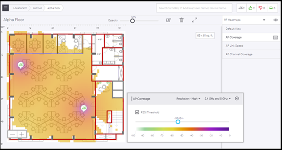
AP Coverage View allows user to view AP coverage for the selected floor plan. AP coverage view has floating windows that allow user to select resolution, frequency band, RSSI threshold configuration and color palette corresponding to different RSSI value range.
There are two types of filters available, Resolution and frequency. On basis of these filters the AP Coverage view can be modified. To know more about these filters refer Resolution and Frequency Filters topic. RSSI Threshold check box if checked, allows user to view the RSSI threshold coverage as per the currently configured value for RSSI threshold. Otherwise coverage view will be shown as per the default RSSI configuration from RSSI color palette. User can change the RSSI threshold value by adjusting the scale.
- Select FLOOR PLANS tab from the left panel.
- Select the existing floor plan for which you wish to see the AP Coverage.
- Choose RF Heatmaps option from the right hand side panel.
- Select AP Coverage.

Access Point Link Speed View
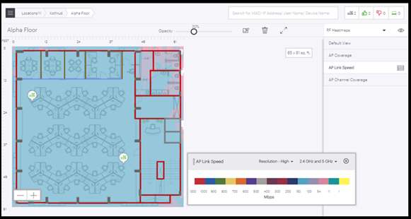
AP Link Speed view allows user to view the AP link speed for the selected floor plan. AP link speed view has floating windows that allow user to select resolution, frequency band and a color palette corresponding to different link speed value range.
There are two types of filters available, Resolution and frequency. On basis of these filters the AP Coverage view can be modified. To know more about these filters refer Resolution and Frequency Filters topic.
- Select FLOOR PLANS tab from the left panel.
- Select the existing floor plan for which you wish to see the AP Link Speed.
- Choose RF Heatmaps option from the right hand side panel.
- Select AP Link Speed.

Access Point Channel Coverage View
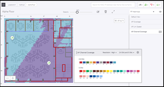
AP Channel Coverage View allows user to view the AP channel coverage for the selected floor plan. AP channel coverage has floating windows that allow user to select resolution, frequency band and a color palette corresponding to different channels.
- Select FLOOR PLANS tab from the left panel.
- Select the existing floor plan for which you wish to see the AP Channel Coverage.
- Choose RF Heatmaps option from the right hand side panel.
- Select AP Channel Coverage.

Resolution and Frequency Filters
Resolution and Frequency are the two filters available for heat maps. These filters are available for all the views except Default View.
Resolution Filter
- Low: Accuracy of calculation and visualization will be low but it will take less time to show the result.
- Medium: Accuracy of calculation and visualization will be moderate and will take moderate time to show the result.
- High: Accuracy of calculation and visualization will be highest but it will take maximum time to show the output.
Frequency Filter
- 2.4 GHz: Data for only 2.4 GHz AP radios will be shown.
- 5 GHz: Data for only 5 GHz AP radios will be shown.
- 6 GHz: Data for only 6 GHz AP radios will be shown.
- All bands: Data for 2.4, 5, and 6 GHz AP radios will be shown.
