Maintenance and Field Replacement
There is a linecard and supervisor removal tool to facilitate the removal and installation of linecards and supervisor modules. Use the tool as a sleeve on the release handle. It is mounted on the supervisor module Front Panels. Replace the tool after each use.
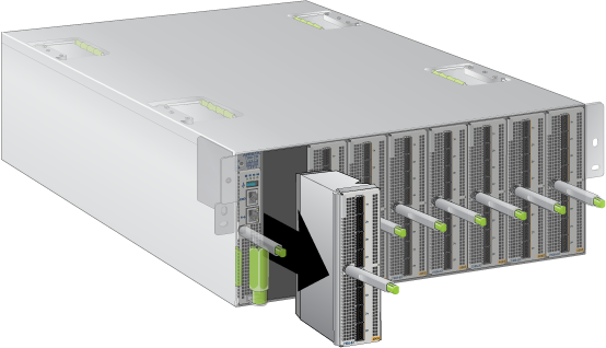
Switch Card Module
The switch card module is accessible from the rear of the switch as shown in Rear Panels. Refer to the following figure for more details on the removal and replacement of the switch card module.
| 1 | Switch Card Release Handle (Swing Arm) |
| 2 | Switch Card Release Buttons |
The module includes lock-levers that secure it to the chassis. The module and the lock levers are easily damaged by improperly removing, inserting, or handling. Use caution while lifting or moving the module after it is removed from the chassis.
Removing Switch Card Module
The switch card module can include the fans and the power supplies. The release handle is a swing arm that is used for unseating and seating the switch card module.
Follow the steps listed below to remove the switch card module from the switch chassis.
- Ground yourself with an ESD wrist strap.
- Push the switch card release buttons.
- Move the release handle (swing arm) down.
- Carefully, remove the switch card module from the chassis while supporting it through the process.
Inserting Switch Card Module
The module insertion process is the inverse of the removal procedure. Follow the steps listed below to insert the switch card module into a chassis.
Power Supplies
The power supplies are accessible from the rear of the switch (Rear Panels). Refer to the following figure for more details on the removal and replacement of a power supply unit.
The following steps are required when removing power supplies from a switch.
Removing a Power Supply
- Push the power supply release handle and remove the power supply as shown in the figure below.
Figure 2. Remove power supply .png) Note: PSUs are hot swappable and do not require the removal of the switchcard. The illustration shows the switchcard removed for clarity.
Note: PSUs are hot swappable and do not require the removal of the switchcard. The illustration shows the switchcard removed for clarity.
Installing a Power Supply
You must make space for installing the power supply by removing an existing one (Removing a Power Supply).
Fan Modules
The fan modules are accessible from the rear of the switch as shown in Rear Panels. Refer to the following figure for more details on the removal and replacement of a fan module.
Removing a Fan Module
The following steps are required when removing or replacing fans from a switch.
- Pinch the fan module release lever and slide the fan module out of the switch as shown in the figure below.
Figure 3. Removing fan module .png) Note: Fans are hot swappable and do not require the removal of the switchcard. The illustration shows the switchcard removed for clarity.
Note: Fans are hot swappable and do not require the removal of the switchcard. The illustration shows the switchcard removed for clarity.
Installing a Fan Module
You must make space for installing the fan module by removing an existing one (Removing a Fan Module).
Supervisor Module
The supervisor module is accessible from the front of the switch as shown in Front Panels. Refer to the following figure for more details on the removal and replacement of a supervisor module.
Removing Supervisor Module
The supervisor module has a release handle with a push button latch indicator. The ejector tool works for both the linecards and the supervisor.
Perform the following steps to remove the module.
- Gently remove the supervisor module by pulling outwards once the tool rotation stops moving the supervisor module outwards (approximately five turns).
.png)
Installing Supervisor Module
You must make space for installing the module by removing an existing one (Removing Supervisor Module). Perform the following steps to install the module.
Linecards
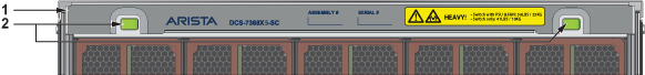
The linecards are accessible from the front of the switch as shown in Front Panels. The linecards are hot-swappable. You must take into account that the linecard you are inserting is compatible with the switch and the linecard that you are replacing. Refer to the following figure for more details on the removal and replacement of a linecard module.
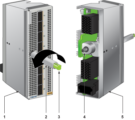
| 1 | Linecard Metal | 3 | Latch Indicator Button | 5 | Linecard Metal |
| 2 | Ejector (Release) Handle | 4 | Engaging and Aligning, Geared Screw |
Removing Linecard
Perform the following steps to remove a linecard.
- Gently remove the linecard by pulling outwards.
Installing Linecard
You must make space for installing the linecard by removing an existing one (Removing Linecard) from a linecard slot available on the switch.
Optical Transceivers
For more information about supported optical transceivers and how to remove or install them, refer to https://www.arista.com/en/products/transceivers-cables.