The configuration guide is no longer being updated. Please refer to the CloudVision Help Center going forward.
Non-Author Change Control Review
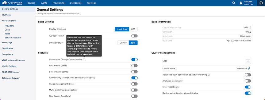
The non-author change control review feature enforces change control reviews by someone other than the author.This ensures that two separate people have reviewed a change before it is approved and can be rolled out onto the network.
Enabling Non-Author Change Control Review
Note: This feature can only be enabled from the Cluster Management role.
From the General Settings menu, select the Non-author Change Control review toggle to enable the feature.
Figure 1. Enabling Non-Author Change Control Review
Pending and approved changes are displayed in the Change Control screen located in the Provisioning tab.
When the feature is enabled, the user making the change (author) will not be allowed to modify the approval status (approve/disapprove) of their own changes.
The configuration guide is no longer being updated. Please refer to the CloudVision Help Center going forward.
Change Control Template
Change Control Template allows you to build and structure common change control
operations, and to repeat them without having to rebuild or re-specify the actions and
sequences. The template is easily modified which enables you to execute evolving change
control operations quickly and efficiently.
To configure a Change Control Template, use the Action Bundle and Stage Rule tools. Each
Stage Rule depends on an Action Bundle for its content, so at least one Action Bundle
must be created before you can start using Change Control Templates.
Stage Rules
A Template is defined by a list of Stage Rules. Stage Rules can be executed in Series
or Parallel at the root of the change control. Each Stage Rule is linked to one
Action Bundle, which supplies the content for that stage.
Action Bundles
An Action Bundle is a specific sequence of actions that contain up to one task action
and a limitless number of non-task actions. Action Bundles are reusable across
multiple Templates and allow you to construct a specific sequence of actions without
defining the tasks or devices that they will be applied to.
Creating and implementing a change control event with a Template, requires five basic
steps:
Create or select one or more Action Bundles.
Assign each Action Bundle to a Stage Rule.
Configure the Stage Rules of the Template.
Save the Template.
Apply the Template in Change Control.
Once the Template has been saved, it will be available to apply repeatedly. For
future change control operations with the same actions and sequence, you will only
need to follow Step 5.
Action Bundles
Action Bundles are a determined sequence of actions that can include up to one task
action and an unlimited number of non-task actions. The Action Bundles are assigned them
to the Stage Rules of a Template, which means that you will want to create, edit, and
delete Action Bundles.
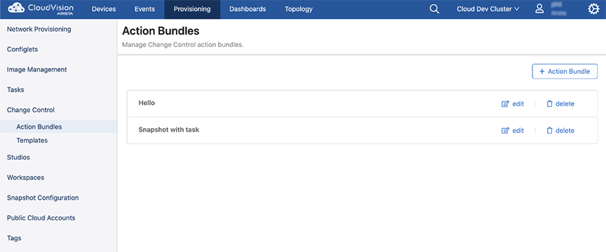
You can manage Action Bundles by selecting Provisioning in the navigation bar and
then selecting Action Bundles.
Figure 1. Action Bundles
Creating a New Action Bundle
When creating a new Action Bundle, one task action and unlimited non-task actions can
be added.
Click + Action Bundle
In the side panel that opens, enter a bundle name and an optional description
and then click the Add Action menu.
Select an action from the available list.
Figure 2. Select an Action
Note: Every action except for Execute Task is a non-task action. You can
only add one task action for each Action Bundle.
Depending on the action type selected, you may have some additional options for
what devices you can assign the action to.
Note: The task action will always have its device assigned in the Stage Rule
of the Template that the Action Bundle is applied to. For more
information on these options, see Device Placeholders and Static Arguments.
Select the actions of this Action Bundle to be executed in series or
parallel.
Review the list of actions, and click Save. The Action Bundle will now
be available to be assigned in the Stages Rules of Templates.
Editing an Action Bundle
To edit an Action Bundle.
Note:Upon saving the edits, any template that the Action Bundle is a component of
will be updated.
Click Edit on the Action Bundle to be modified.
Figure 3. Editing an Action Bundle
From the side panel, add new actions, modify the order of existing actions, or
delete existing actions.
Click Save to update the Action Bundle.
Deleting an Action Bundle
Note: The following procedure does not remove the Action Bundle from any assigned
Template.
Select Delete.
Figure 4. Deleting an Action Bundle
A modal that will ask you to cancel or remove. Click Remove.
Device Placeholders and Static Arguments
When creating or editing the actions of an Action Bundle, you can assign device
placeholders instead of specific devices to the action. These placeholders are then
defined when the Action Bundle is added to the Stage Rule of a Template. This gives you
the flexibility to assign the same Action Bundle to multiple Templates.
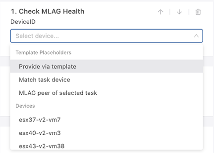
The following is a complete list of device placeholders, along with a sample list of
devices you can statically apply the action to:
Figure 5. Device Placeholders
The placeholders available to you vary based upon the combination of action types that
you have already selected. Consequently, additional placeholders may become available
for an action after you have added more actions to the Action Bundle. Specifically,
‘Match task device’ and ‘MLAG peer of selected task’ only appear when the Action Bundle
contains a task.
Provide via Template
When this action is assigned as a placeholder, you will configure it when building
the Template. You can use the Device Filter field in the Stage Rule that the Action
Bundle is applied to.
Figure 6. Provide via Template
Select one of the following options:
All Devices in Change Control: This option matches all devices
associated with the change control (defined by which tasks are linked to
the change control)
Regular Expression: This option allows you to select certain
devices from Change Control by defining a regular expression to evaluate
against the device hostname
Match Task Device
An Action Bundle can contain a maximum of one task action. The device of the task is
assigned in the Template using the Device Filter field.
When configuring the Action Bundle, a non-task action with the placeholder Match Task
Device can be assigned. This means that the device associated with the task will be
applied to the non-task action.
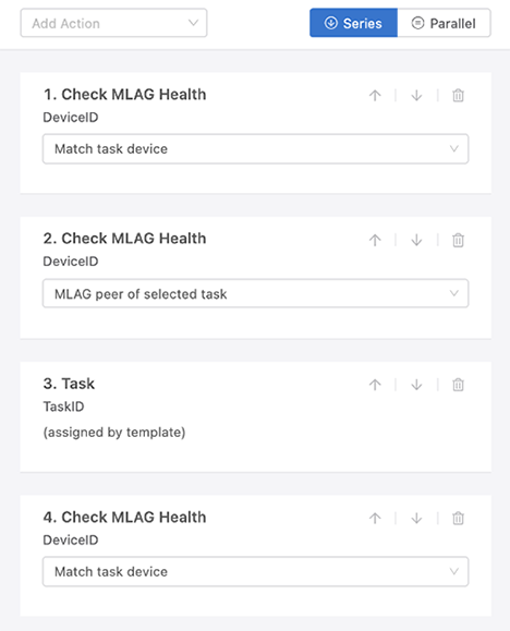
MLAG Peer of Selected Task
This placeholder enables you to sequence MLAG upgrades. You can run non-task actions
on the MLAG peer of the device that the task in the Action Bundle is assigned to.
By using this placeholder, the MLAG Health Check can be run against the MLAG peer
before running the task.
The following figure is an example of how actions can be arranged so that the MLAG
health of both the task device and the task device’s MLAG peer are checked before
running the task. The last action checks the MLAG health of the task device after
the task has been performed.
Figure 7. MLAG Peer of Selected Task
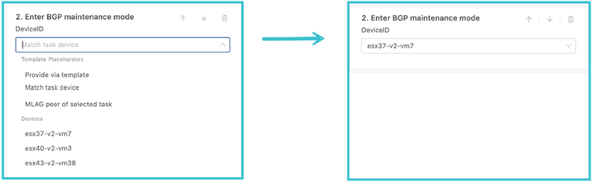
Static Action Arguments
Static arguments can be applied in an Action Bundle by assigning certain non-task
actions with a specific device. This enables you to always have a particular action
run against a specific device when the Action Bundle is applied to a Stage Rule in a
template.
Figure 8. Static Action Arguments
Templates
Action Bundles will be assigned to a Template. With the Template you will bundle and
sequence specific actions and group those action bundles into stages to define the
upgrade sequence.
Note:Applying a Template to a change control is a single operation. The Template is
not permanently linked to the change control; therefore, making changes to a
Template after it has been applied to a change control will have no effect on the
existing change control.
A Template can be applied multiple times. Each time the existing structure
will be completely overwritten, and only the tasks will remain as the sole
input to the Template.
This feature cannot be used to craft arbitrarily complex change controls,
and advanced users may want to leverage the Change Control API to construct
custom layouts.
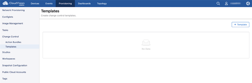
Accessing Templates
Select Provisioning and select Templates. The following screen will be
displayed.
When creating a new Template, an unlimited number of Stages Rules can be added using
at least one Action Bundle.
Select + Template from the Templates screen.
Each Stage Rule is associated with a single Action Bundle.Select an Action
Bundle from themenu or create a new one.
Figure 10. Create a New Template
Once you have assigned an Action Bundle, complete any additional fields
associated with the specific Action Bundle.
Note: If the Action Bundle contains device placeholders, a Device Filter
will appear. This is used to define which devices will be applied to
this Action Bundle.
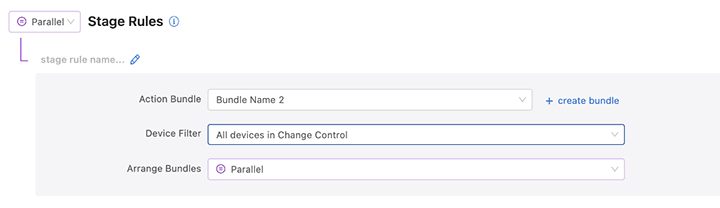
A sub-stage will be created for every populated Action Bundle. Arrange the
sub-stages in Series or Parallel.
Figure 11. Stage Rule
You can repeat Steps 2-4 to create a Stage Rule for each Action Bundle to be
added to the Template, and then arrange the order of the Stage Rules.
Figure 12. OrderStage Rules
Note: The same Action Bundle can be applied to multiple stages, each with a
unique Device Filter.
Set the Stage Rules to execute in Series or Parallel.
Figure 13. Set Stage Rule
When done, select Save Template.
Edit a Template
Note: Any changes made to a Template will not be updated for any change control
operations it has been applied to. The Template will need to be
reapplied.
Click Edit on the Template to modify. The Template screen will display
its current Stage Rules and details, how they are ordered, and the manner in
which they will be executed.
Figure 14. Edit a Template
Edit any of the details by amending the fields, using the up and down arrows,
or deleting Stage Rules.
Click Save Template when done.
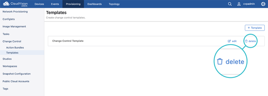
Delete a Template
Click Delete on the Template you wish to remove.
Figure 15. Delete a Template
Note: Deleting a template will not affect change controls that were
previously generated using that template.
Creating a New Change Control with a Template
Follow these instructions to create a change control and apply a Template at the same
time.
Select Tasks or Change Control under the Provisioning tab, and
click Create Change Control.
In the screen that is displayed, enter a name for the change control and select
the tasks that should be included in the change control.
To build the change control with a Template, click Template.
Figure 16. Creating a New Change Control with a Template
From the menu, select a Template and select Create Change Control.
The Change Control screen will be displayed. Revise to the change control
format, review and approve the proposed changes as needed.When done execute
the network changes.
Applying a Template to an Existing Change Control
If a change control has been created but not approved or executed, you can apply a
Template to it.
Select Change Control, and select the desired change control from the
Open Change Control list.
The Change Control edit screen of the selected change control is displayed.
Click Select a Template to open up a menu of your Templates.
Select the Template that you want to apply to the change control and click
Apply Template.The Template configuration will be added to the change
control for review and approval.
Note: Applying a Template to a change control operation is a single
operation. Any changes made to the Template will not be automatically
applied to the change control.
The configuration guide is no longer being updated. Please refer to the CloudVision Help Center going forward.
Creating and Managing Custom Actions
The Actions menu in the CloudVision portal enables you to create and manage frequently used actions in the Action Bundles and Change Control operations menu.
Apart from the existing set of actions, a new suite of actions is added to perform additional change control operations on your desired devices. In the Actions menu, you can view the arguments of built-in actions and create and manage custom actions, which you can apply in a change control operation. Creating your own custom actions enable you to execute actions specific to your network, which you or another CloudVision user has defined. Additionally, provisioning devices using a change control operation enables you to have granular control over the actions during the change control operation.
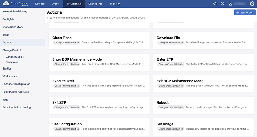
Starting with the 2023.2.0 release, the following new actions are available in the Actions menu.
Table 1. New Actions in Release 2023.2.0
Actions
Description
Clean Flash
Creates space on a device by deleting files in the flash directory.
Download File
Download files from CloudVision to a device.
Enter ZTP
Puts the device in zero touch provisioning mode.
Exit ZTP
Removes the device from zero touch provisioning mode.
Reboot
Reboots the device.
Set Configuration
Applies the configuration on the device.
Set Image
Installs an image on the device.
See image below for the newly added actions.
Figure 1. New Actions in Release 2023.2.0
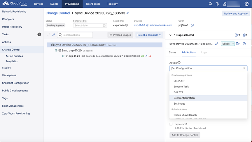
You can use the above actions through the Change Control menu for configuring change control operations as shown in the image below. The new provisioning actions are available under Provisioning Actions or Built-In Actions and function like any pre-existing built-in action.
Figure 2. Change Control Actions
When you select an action, you must also choose the devices to run the action against. See below sections for details on each action.
Clean Flash Action
The Clean Flash action deletes the files from flash memory on a device. You must define the file specifications and the devices that the action should run against. From the Change Control Actions page,
Select Clean Flash as in the image below:
Figure 3. Change Control - Clean Flash
Enter a File Spec. By default, flash:*swi is populated.
Select one or more devices to run the action against.
Click Add to Change Control.
Download File Action
Using the Download File action, you can download images and extensions from the Image Repository onto a device. This enables you to preload files on a device before updating the image or extension and helps in saving time while executing a change control for updating the device.
From the Change Control page, select the Download File against a device, it downloads the selected file to the flash directory of the device. See image below:
Figure 4. Download File Action
Select an image or extension from the EOS Software Image Filename drop-down menu. All files added to the Image Repository are available from the drop-down menu. If your desired software file is not available in this list, add it to the Image Repository and try again.
Select the devices to run the action against from the Run action against selected devices field.
Click Add to Change Control. The selected file gets downloaded onto the device.
Enter ZTP Action
Choosing this action puts a device in Zero Touch Provisioning (ZTP) mode.
From the Change Control page, select the Enter ZTP action. See image below:
Figure 5. Enter ZTP Action
Select the devices to run the action against from the Run action against selected devices field.
Click Add to Change Control. The selected devices are now in ZTP mode.
Exit ZTP Action
The Exit ZTP action gets the device out of ZTP mode.
From the Change Control page, select the Exit ZTP action. See image below:
Figure 6. Exit ZTP Action
Select the devices to run the action against from the Run action against selected devices field.
Click Add to Change Control. The selected devices now exit the ZTP mode.
Reboot Action
You can reboot a device by using the Reboot action. As a result, the selected devices stop forwarding traffic until the devices are completely restarted.
From the Change Control page, select the Reboot action. See image below:
Figure 7. Reboot Action
Select the devices to run the action against from the Run action against selected devices field.
Click Add to Change Control. The selected devices are rebooted.
Set Configuration Action
The Set Configuration action applies the designed configuration to a device. This action reduces the time required and enhances the device configuration process significantly. This action computes a delta configuration between the designed configuration and the running configuration on the selected device. The delta configuration captures the sequence of commands that should be applied to the running configuration of the selected device so as to transform the configuration into the designed configuration. This configuration push is an atomic transactional process, where only the delta commands are parsed and evaluated by AAA, thereby saving significant time in completing the configuration process (that is, without having to process the entire designed configuration on the selected device).
The Set Configuration action is efficient in comparison to the Update Config task when:
Per-command authorization and accounting are enabled on the device.
The designed configuration is large.
The difference between the designed configuration and the running configuration is smaller than the designed configuration (that is, the delta is relatively small).
Note: If the delta configuration does not match with the designed configuration, then a complete push of the designed configuration is automatically done by the Set Config action.
From the Change Control page, select the Set Configuration action. See image below:
Figure 8. Set Configuration Action
From the Config Source drop-down menu, select the type of configuration that you want to apply from:
Designed Configuration: Pushes the designed configuration from CloudVision onto the selected device.
Running Configuration: Rolls back the configuration to a previous running configuration based on the provided timestamp.
Select the devices to run the action against from the Run action against selected devices field.
Click Add to Change Control. The selected devices are updated with the new configuration.
Guidelines to Troubleshoot for Set Configuration Action
If the Set Configuration action takes more than a reasonable time to execute on a device, then explore the following possibilities and take action accordingly:
How big is the delta configuration in comparison to the designed configuration?
If the delta configuration is almost as same as the designed configuration, then, there might not be any significant improvement in configuration push time. This is because when the designed configuration is being pushed on a switch for the first time, all the lines in the designed configuration are also added to the switch.
Is command authorization and accounting enabled on the switch?
When AAA is enabled on the switch, each line in the delta configuration is parsed through AAA. In this case, the performance of the AAA server should be checked to see if that is taking a significant amount of time.
Was delta configuration successful?
If the delta configuration is unsuccessful, then the entire designed configuration gets pushed, resulting in longer than expected configuration push times. Check the Change Control logs to see if the delta configuration push failed and the reason for the failure.
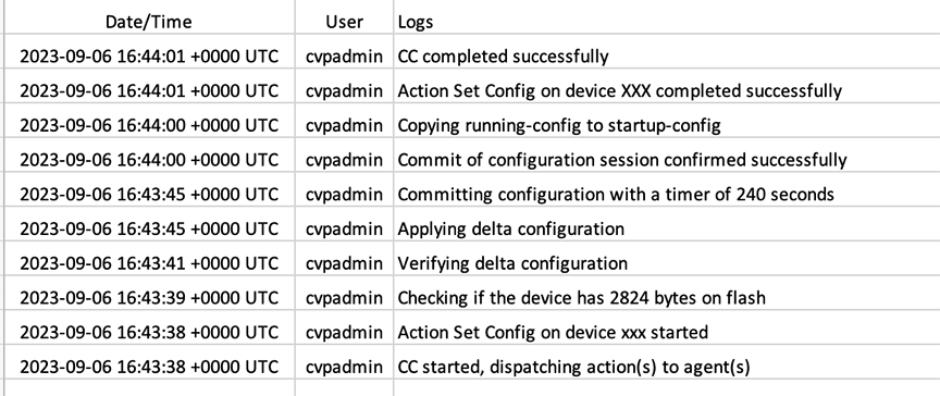
You can view the action logs in Change Control. These logs display any exceptions, errors, or warnings when executing the various actions. Below is an example of a successful log file:
Figure 9. Change Control Success Log Sample
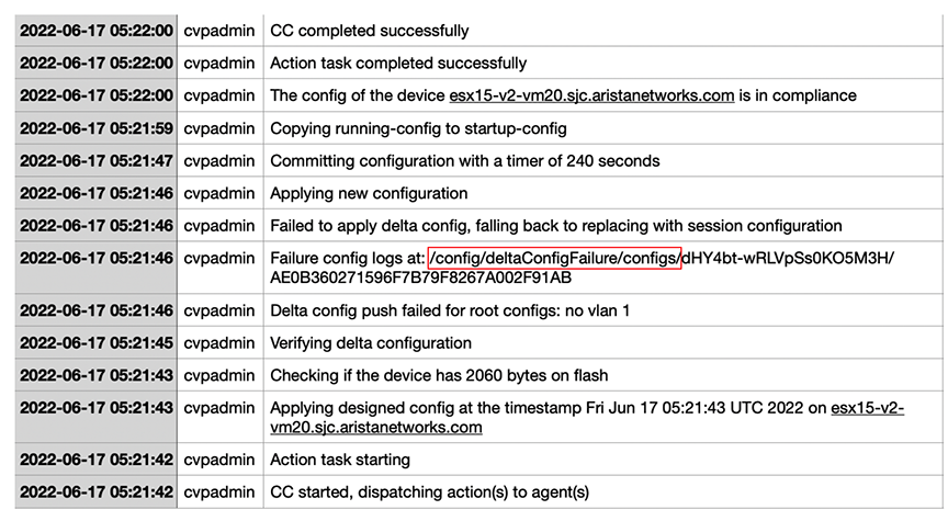
Below is an example of a Change Control log file where the action failed:
Figure 10. Change Control Log - Failure
The log file contains the path /config/deltaConfigFailure/configs/<ccID>/<deviceID>, where you can find the failure details. In the log files, you can find three types of messages as below:
Exceptions: In these types of messages, you can view both the expected configuration (designed config) and the actual config during verification in the form: “EXPECTED:...GOT:…”. This message helps you to determine which configuration lines did not run as expected. See below section for details on Exceptions.
Errors: If you see an error for a particular command, it means that this command was not added or deleted resulting in the failure of the delta configuration push.
Warnings: A warning for a particular command on a specific device helps you to debug why the actual configuration after applying the delta configuration is different from the expected configuration. Note that some warnings may be unrelated to the failure.
What are Exceptions?
An exception occurs when the Set Configuration action fails to remove some running configuration from the selected device. This occurs for certain types of EOS commands, where the action may run, but the delta configuration that is pushed by the Set Configuration action fails and CloudVision subsequently pushes the entire designed configuration onto the device. You must configure the Exceptions separately to resolve the issue.
For example, an exception can occur for a command, switchport port-security
violation protect. Without any additional configuration from the user, the Set Configuration action removes the command by using the default switchport port-security violation protect command. As this is an invalid command the configuration does not get removed. As a result, the Set Configuration action fails and pushes the complete designed configuration on the device.
How to View the Exceptions
To view the exceptions occurring due to the Set Configuration action, go to Settings > Telemetry Browser and select cvp under Application Datasets. See image below:
Navigate to path /config/deltaConfigExceptions/
As of the 2023.2.0 release, you may see one exception related to command parameters, that is, the parameters are dropped by prepending default. For example, to delete the command: switchport port-security violation protect, the command should be default switchport
port-security.
How to add custom exceptions
You can add custom exceptions for the Set Configuration action in CloudVision by using the REST API commands. To add an exception to the path config/deltaConfigExceptions/paramCommands, type:
The Set Image action enables you to update a device with a selected image. You can select the images available in the Image Repository only. You can also select the device reload mode that includes the Smart System Upgrade (SSU) options.
When using this action, you can also use the Preload Image feature that creates a separate change control operation. That operationdownloads the image files onto selected devices and enables the Set Image action to run faster by skipping the download image step. See image below:
From the Change Control page, select the Set Image action. See image below:
Figure 11. Set Image Action Page1
Select an Image Source (see image below):
Designed Image: To install the designed image from CloudVision on the selected device (s).
Running Image: To roll back to a previous running image on the device by using the selected time from timepicker.
Figure 12. Set Image Action - Image Source Options
Select a Reload Mode (see image below):
Figure 13. Set Image Action - Select Reload Mode
Smart System Upgrade (SSU) minimizes traffic loss during image upgrades. SSU leverages protocols capable of graceful restart and minimizes traffic loss during upgrades. Select one of the Reload Mode options from the drop-down menu:
Normal: This option does not use SSU. The device reboots and traffic forwarding stops until the device is restarted.
SSU Only: This option enables CloudVision to first check for any warnings or errors by using the show reload
fast-boot command. If there are any errors or warnings, the upgrade attempt fails and the errors and warnings are reported back to the user. If there are no errors or warnings, then reload fast-boot now command is executed, and the device attempts an SSU.
SSU Only Ignore Warnings: When you select this option, CloudVision first checks for any errors by using show reload
fast-boot command. If there are any errors, the upgrade attempt fails and the errors are reported back to the user. If there are only warnings, the SSU upgrade proceeds and CloudVision issues a reload fast-boot now command and an SSU is attempted.
SSU Preferred: When you select this option, CloudVision first checks for any warnings or errors using the show reload
fast-boot command. If there are any errors or warnings, then CloudVision aborts the SSU and falls back to Normal reload mode.
SSU Preferred Ignore Warnings: When you select this option, CloudVision first checks for any errors or warnings using the show reload fast-boot command. If there are only warnings, then SSU is attempted. If there are any errors, Normal reload is attempted.
Select the devices to run the action against from the Run action against selected devices field.
Click Add to Change Control. The selected devices are updated with the new image.
The configuration guide is no longer being updated. Please refer to the CloudVision Help Center going forward.
Authentication and Authorization (CVP)
Authentication determines if the provided user credentials (username/password) are correct. If authentication succeeds, the user is logged in.
Authorization determines what operations the user can perform after login. Authorization can be for no access, read access, or read and write access.
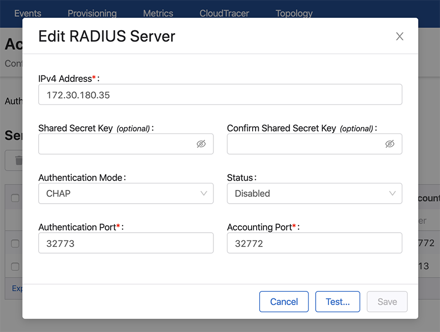
In the Access Control page, the type of Authentication and Authorization can be defined. AAA servers are defined in this page.
This module guides account management administrators to manage AAA servers, user accounts, and user roles. It provides the functionality required to manage all aspects of user accounts.
Note: Only account management administrators have the permissions to manage accounts.
Note: If AAA is enabled and you attempt to perform image bundle upgrades without having
these required access rights, the upgrade will fail and the following error occurs:
For TACACS+ there is no vendor specific code, just different strings.
Note: CloudVision support for TACACS+ servers can be affected with the
setting of the “service” parameter. Some TACACS servers may require "service =
shell" instead of "service = exec" in the TACACS+ configuration
(tacacs.conf).
This example configures user “bob” in the admin group and specifies
certain attributes. It specifies a "cvp-roles" attribute for the CloudVision
role name (it can also be a list of roles).
A. tacacs.conf
group = admingroup {
 default service = deny
 service = exec {
default attribute = permit
priv-lvl = 15
cvp-roles = network-admin
 }
	enable = nopassword

}
user = bob {
 login = cleartext "secret"
	member = admingroup
}

B. CVP AAA settings
C. Switch AAA configlet
CISCO ACS
To ensure that authentication and authorization work properly, complete the following
procedures.
Creating Identity Groups and Users
Select Users and Identity Stores, and then select Identity
Groups.
Make sure a group named <user-group> exists. If this group does
not exist, add it.
Add new users under the group named <user-group>.
Creating a Shell Profile using ACS
Go to the Policy Elements page.
Select Device Administration > Shell Profiles.
Click the Create button to create a new shell profile.
Select the Custom Attributes tab, and then add a new mandatory
attribute named “cvp-roles”.
Specify one or more of the following values to the new “cvp-roles”
attribute:
network-admin
network-operator
Note: If you have created custom role(s) under
CVP Account Management, you can use them.
Check to make sure that under the “Common Tasks Attributes” table, “Assigned
Privilege Level” and “Max Privilege Level” are added by default with and the
specified value is 15. Also, verify that requirement is set
“Mandatory.”
Creating and Modifying Access Policy
Go to the Access Policies section and select the Default Device Admin
policy.
Make sure that “Allow PAP/ASCII” option in the Authorization section is
enabled (selected).
In the Authorization section, create a new rule named “Rule-1”.
Make sure that the status of the new rule (“Rule-1”) is Enabled, and set the
identity group as “<user-group>”.
Select the shell profile that outlines the cvp-roles for all users under the
group named <user-group>.
Note: Alternatively, you can set add shell profile in the “default rule”
section.
Make sure that “Service Selection Rules” (under the “Access Policies”
section), is using the policy named “Default Device Admin”. The policy
should be listed in the “Results” column of “Service Selection Policy”
table, and the “status” column should be green, indicating that the policy
is enabled.
Note: The shell profile should be
automatically applied to all users under the ground named
<user-group>.
Supported TACACS Types
CloudVision Portal (CVP) supports different types of TACACS. Table Supported TACACS
Types lists the supported types of TACACS, including the following information
for each TACACS type:
Supported version
Service shell (whether it is supported for each type)
Service exec (only the following attributes are supported):
The configuration guide is no longer being updated. Please refer to the CloudVision Help Center going forward.
Upgrading Extensible Operating System (EOS) Images
CloudVision Portal (CVP) provides the functionality to upgrade the EOS image on a device.
Typically, you upgrade the image on a device to change the version of the image from an
unsupported image version to a supported image version.
You upgrade device images by associating an EOS image with a device or a container (the
association is referred to as an image association). Image associations follow the same
container inheritance rules as configlet associations. This means that the image you
select to be associated is automatically inherited (assigned) to all devices under the
level in the hierarchy at which you associate the image.
Note: When performing an image push, CloudVision checks if the target EOS image is already
present on flash. If the .swi file is available, CloudVision uses
the same file instead of downloading a new image from the network. This reduces network
costs and time incurred during image upgrades.
This example shows the behavior of image associations in a multi-level
network hierarchy. The hierarchy in this example contains a tenant container
named Demo-Lab. The Demo-Lab container has five child containers named CVX,
Host-TOR1, Leaf, Spine, and TOR2.
Figure 1. Same Task Scheduled for Every Device in CVX Container
Based on the rules for image association inheritance, the Demo-Lab
container could have selected the
4.18.8M device EOS image.
Figure 2. Example of image Association (Example 1)
The CVX container could override that image selection
(4.18.8M image) for its devices by selecting the
4.20.7M image. As a result, all of the devices under
CVX are assigned the
4.20.7M image, and the devices under Host-TOR1, Leaf,
Spine and TOR2 inherit the
4.18.8M image from the Demo-Lab container.
Figure 3. Example of Image Association (Example 2)
If an image association is changed at any level, and the change is saved
in the
Network Provisioning page, the following occurs:
The change impacts all
devices under that level.
A task is automatically
created to upgrade the impacted devices.
For example, if the image selection was removed at the CVX level, the
following would occur:
All of the devices under the
CVX level would inherit the Demo-Lab image.
A task would be scheduled
for every device in CVX to use the Demo-Lab image.
When several image association tasks are scheduled to be completed,
use the following steps to execute the tasks. These steps help you to execute
the tasks more efficiently.
Search for Pending in the Tasks page to find the tasks to be executed
(status is “Pending”).
Select them all by clicking the checkbox next to the Task ID
heading.
If the search results returns multiple pages of tasks, then click
the checkbox at the top of each page to select the tasks so they can be
executed.
Figure 4. Selecting Multiple Tasks to be Executed
Click the
Play icon to execute the selected tasks all at once.
The configuration guide is no longer being updated. Please refer to the CloudVision Help Center going forward.
Creating Image Bundles
Creating image bundles is a key image management task. You create image bundles so that
you have supported image versions available to be assigned to devices in your CVP
environment.
Note: An image bundle must have one .swi file. Extensions are
optional (not required for image bundles), but you can add one or more extensions to
an image bundle.
Pre-requisite: To ensure that you include valid (supported) EOS images in the
bundles you create, make sure you validate the images you want to include in the bundle
(see Validating Images).
Complete the following steps to create an image bundle:
Creating a Bundle by Tagging Existing Image Bundles
CloudVision Portal (CVP) enables you to create a new image bundle by
tagging existing image bundles. This prevents you from having to import the
same image again to create another bundle.
Go to the
Image Management
page.
Click the “+” icon and then the Disk icon.
This opens the Images dialog, which lists all of the available images. Figure 2. Images dialog
Search for the desired image.
Select the image and click
Add to add the image to the bundle.
The image will be displayed in the grid of the Create Image Bundle page. Figure 3. Added image shown in Create Image Bundle page
CloudVision Portal (CVP) enables you to create new image bundles
by uploading new images to CVP.
Go to the
Create Image Bundle page.
Click the upload from local icon available next to disk icon.
This opens a dialog to search and upload .swi files from system.
Navigate to the desired .swi file and upload it to CVP.
The upload bar on the page shows the progress of the upload.
Figure 4. Uploading .swi files to CVP (upload in progress)
Click
Save to create the new image bundle.
Adding EOS Extensions to Image Bundles
CloudVision Portal (CVP) enables you to add EOS extensions to
image bundles along with .swi images. Extensions are either .rpm files or .swix
files. You upload .rpm or .swix files using the Images page. Extensions are
optional for image bundles
Note: All selected extensions automatically checked to be installed and running on the device.
The results are available for viewing under the Compliance Overview tab
on Devices page.
Complete these steps to add EOS extensions to an image bundle:
Go to the
Create Image Bundle page.
Click the upload from local icon.
This opens a dialog to search and upload EOS extensions (.rpm or
.swix files) from the system
Navigate to the desired .rpm or .swix files and upload them.
The upload bar on the page shows the progress of the upload. The
extensions you uploaded are shown in the Create Image Bundle page
Select Reboot Required check-boxes for all extensions that require a
reboot.
Click
Save. The extensions are added to the image bundle.
Once the image bundle is assigned to a device, a reboot task will
be generated. The newly added extensions are installed on the device when the
reboot task is executed. Any extensions that were previously installed but are
not part of the current bundle are removed from the device.
The configuration guide is no longer being updated. Please refer to the CloudVision Help Center going forward.
The Bundle Information Page
The Image Management page provides high-level information about an image bundle (for
example, the number of containers to which an image bundle is associated, and the number
of devices to which an image bundle is assigned).
To view more detailed information about image bundles, use the Bundle Information page,
which you can open from the Image Management page.
Complete these steps to open the Bundle Information page.
Go to the Image Management page.
Click the name of image bundle for
which you want to view information.
Figure 1. Opening the Bundle Information page
The Bundle Information page appears, showing information for the selected image
bundle. Use the following tabs to view specific information about the selected image
bundle.
The Summary tab provides basic information about the Image Bundle. It
also provides options to go back to the Image Management page, to open
the dialog used to update image bundles, and to delete corresponding image
bundle and its extensions.
Figure 2. Summary tab
For details on the steps used to edit image bundles and delete image
bundles, see:
The Logs tab provides complete information on the image assignment to
devices and execution details. It also provides the option to go back to the
Image Management page.
Figure 3. Logs tab
Applied Containers Tab
The Applied Containers tab displays the details on the containers to
which the bundle has been applied. It also displays the name of the user that
applied the bundle and the date it was applied.
Figure 4. Applied Container tab
Applied Devices Tab
The
Applied Devices tab displays the details on the devices to which
the bundle is assigned, along with other information such as the parent
container for the device, and the name of the user that applied the bundle and
the date it was applied.
The configuration guide is no longer being updated. Please refer to the CloudVision Help Center going forward.
Partial Configuration Management
The partial configuration management feature specifies parts of configuration that should be managed by CVP. Each line in the configuration is classified in the following three categories:
Managed - These configuration lines must be managed only by CVP.
Note: Managed configuration lines are considered config compliant only when they synchronize with the designed and running configuration. In other words, updating managed configuration lines via non-CV sources will mark the device as non-compliant and cannot be reconciled by default. Only the user can reconcile these lines.
Unmanaged - These configuration lines can't be managed by CVP.
Note: Unmanaged configuration lines can be added to the running configuration via non-CVP sources without marking the device as non-compliant. These lines are ignored by CV during computation of configuration compliance and can never be reconciled.
Unspecified - These configuration lines are by default managed and reconciled by CVP. They are not marked as managed or unmanaged by CVP.


/Same%20Task%20Scheduled%20for%20Every%20Device%20in%20CVX%20Container.png)
/Example%20of%20image%20Association%20(Example%201).png)
/Example%20of%20image%20Association%20(Example%202).png)
/Selecting%20Multiple%20Tasks%20to%20be%20Executed-2.png)
/Create%20Image%20Bundle%20page.png)
/Images%20dialog.png)
/Added%20image%20shown%20in%20Create%20Image%20Bundle%20page.png)
/Uploading%20.swi%20files%20to%20CVP%20(upload%20in%20progress).png)
/Create%20Image%20Bundle%20showing%20uploaded%20extensions.png)
/Opening%20the%20Bundle%20Information%20page.png)
/Summary%20tab.png)
/Logs%20tab.png)
/Applied%20Container%20tab.png)
/Applied%20Devices%20tab.png)
/Updating%20Bundles%20-%20Image%20Management%20Summary%20Screen.PNG)
/Deleting%20Bundles.PNG)