Backup & Restore, Upgrades, DNS NTP Server Migration
This document provides details on how to perform backup and restore operations and upgrading CloudVision Portal (CVP).
This document provides details on how to perform backup and restore operations and upgrading CloudVision Portal (CVP).
CloudVision Portal (CVP) enables you to backup and restore the complete CVP provisioning dataset, including containers, devices, configlets, images, and configlet / image assignments. You can use commands to backup and restore CVP data.
Arista provides a simple script at /cvpi/tools/backup.py which is scheduled by default to run daily to backup CVP data, and retain the last 5 backups in /data/cvpbackup/. Backing up and restoring data saves information about the CVP instance to a tgz file, and then restores the information from the tgz file to a new CVP instance. The CVP commands provide all of the functionality required to complete backup and restore operations.
The current CVP release does not support restoring backups taken from previous CVP releases. If you would like to restore a backup from a previous CVP release, install the previous release, restore the backup, and then upgrade to the current release. After you have successfully upgraded to the current release, take another backup so that you can directly restore that into current main release in the future.
For more information, see:
The basic requirements for backup and restore operations are the same for single-node installations and multi-node installations.
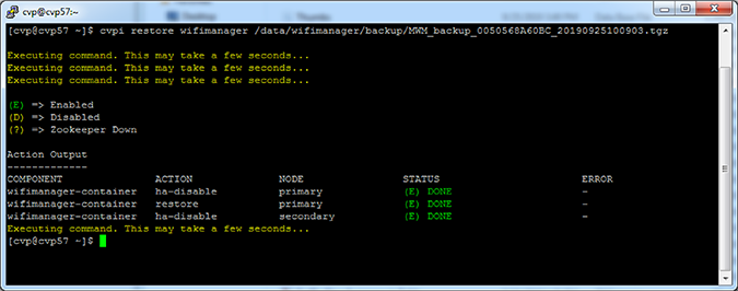
Arista recommends to back up wifimanager regularly and especially before performing any upgrades.
You can restore wifimanager from a backup using the cvpi restore wifimanager </path/to/backup/file> command.
For RMA or recovery issues, contact This email address is being protected from spambots. You need JavaScript enabled to view it..
Backup and restore are CVPI functionalities of CVPI components.
The default directory to save and restore backup data files is /data/cvpbackup.
The default directory for backup/restore log files is /cvpi/logs/cvpbackup.
The default directory for temporary files during backup/restore is /data/tmp/cvpbackup.
The following commands are used to backup and then restore the containers, devices, configlets, images, and configlet or image assignments that are defined in CVP.
cvpi backup cvp[cvp@cvp108 bin]$ cvpi backup cvpcvpi restore cvp cvp.timestamp.tgz eosimages.timestamp.tgzThe cvp.<timestamp>.tgz parameter contains provisioning data
from the DataBase (DB) of the CVP application. The
cvp.eosimages.<timestamp>.tgz parameter contains EOS
images and extensions stored in the DataBase (DB) of the CVP application.
[cvp@cvp108 bin]$ cvpi restore cvp cvp.2019.1.0.tgz cvp.eosimages.2019.1.0.tgzTo check the progress of the backup, tail -f/cvpi/logs/cvpbackup/backup_cvp.20190606020011.log.
CVP backup creates two backup files in the /data/cvpbackup directory for restoration. The eosimages.tgz is generated only when it differs from the currently available copy of the eosimages.tgz, and is an optional parameter for restore if the CVP system already contains the same EOS image.
The cvpi backup command can be run anytime and does not disrupt the cvp application. However, the cvpi restore command will stop the cvp application and disrupt the service for the duration of the restore. If the restore is from a backup on a different CVP system to a new CVP system, it may also be required to on-board the EOS devices or restart the Terminattr daemons on the EOS devices after the restore.
If the cvpbackup directory does not exist in /data when copying the restore files to a newly built VM, you must create it and assign the ownership to the cvp user and group in either of the following two ways:
Login as cvp user and create the cvpbackup directory
Use the su cvp command to login as cvp user and the mkdir -p /data/cvpbackup command to create the cvpbackup directory.
Create the folder as root and change the ownership
Use the mkdir -p /data/cvpbackup command to create the folder as root and the chown -R cvp:cvp /data/cvpbackup/ command to change the ownership of cvpbackup directory and its files to cvp user and group.
Use one of the following commands to verify the ownership of cvpbackup directory:
ls
This example verifies the ownership of cvpbackup directory using the ls command.
[root@cvp-2019 data]# ls -l /data/ | grep cvpbackup
drwxrwxr-x. 2 cvp cvp 236 Mar 16 02:01 cvpbackup
stat
This example verifies the ownership of cvpbackup directory using the stat command.
[root@cvp-2019 data]# stat /data/cvpbackup/ | grep Access
Access: (0775/drwxrwxr-x) Uid: (10010/ cvp) Gid: (10010/ cvp)The following example verifies the ownership of files inside the cvpbackup directory using the ls command:
[root@cvp-2019 data]# ls -l /data/cvpbackup
total 18863972
-rw-rw-r-- 1 cvp cvp 6650171 Mar 14 02:01 cvp.20200314020004.tgz
-rw-rw-r-- 1 cvp cvp 9642441292 Mar 14 02:08 cvp.eosimages.20200314020002.tgzUse the chown command to correct the ownership of cvpbackup directory files.
chown cvp:cvp cvp.<timestamp>.tgz cvp.eosimages.<timestamp>.tgzThe cvp.<timestamp>.tgz parameter contains provisioning
data from the DataBase (DB) of the CVP application. The
cvp.eosimages.<timestamp>.tgz parameter contains
EOS images and extensions stored in the DataBase (DB) of the CVP application.
This example changes the ownership of all cvpbackup directory files.
[root@cvp-2019 data]# chown cvp:cvp cvp.20200319020002.tgz cvp.eosimages.20200314020002.tgzDevices under management must:
The following steps can be taken at any point on an existing cluster as part of preparing for an upgrade to the current version:
Upgrades do not require that the VMs be redeployed, and do not result in the loss of logs.
Upgrades should only be performed on healthy and fully functional CVP systems. Before performing the upgrade, make sure that you verify that the CVP system is healthy.
Complete the following steps to verify the health of CVP.
Use this procedure to complete the fast upgrade of CVP to the current version of CVP.
Pre-requisites:
Complete the following steps to perform the upgrade.
Use this procedure to replace any node of a multi-node cluster. Replacing nodes of multi-node cluster involves removing the node you want to replace, waiting for the remaining cluster nodes to recover, powering on the replacement node, and applying the cluster configuration to the new node.
When you replace cluster nodes, you must replace only one node at a time. If you plan to replace more than one node of a cluster, you must complete the entire procedure for each node to be replaced.
When replacing a node the CloudVision VM that comes with the new CVA might not be the same version as the one running on the other nodes. For more information on redeploying with the correct version refer to: https://www.arista.com/en/qsg-cva-200cv-250cv/cva-200cv-250cv-redeploy-cvp-vm-tool
Check that the XML file is similar as on the other appliances. This can be checked using the virsh dumpxml cvp command.
To ensure that CVP can provide a base level of management, all EOS devices must be running at least EOS versions 4.17.3F or later. To ensure device compatibility supported EOS version advice should be sought from the Arista account team.
CVP should not require any additional EOS upgrades to support the standard features and functions in later versions of the appliance. Newer features and enhancements to CVP may not be available for devices on older code versions.
Refer to the latest Release Notes for additional upgrade/downgrade guidance.
In case of a CV upgrade, services go through the following steps:
You can migrate your DNS / NTP server after you have completed your initial deployment of CloudVision. Migrating the DNS / NTP server is typically done if you want to or need to change the DNS / NTP server that CloudVision currently uses.
For example, if the current CloudVision DNS / NTP server was intentionally isolated during the initial CloudVision installation, you need to migrate the server to make it accessible by external resources.
The process for modifying the DNS / NTP server after the completion of the initial CloudVision installation involves updating the DNS and NTP server entries on each cluster node and modifying the /cvpi/cvp-config.yaml file (on each node) to reflect the updates to the server entries.
Pre-requisites
Before you begin the migration process, make sure that:
Complete these steps to modify the DNS / NTP server.
This document provides configurations steps and examples for supplementary setup procedures for CloudVision Portal (CVP).
There are currently seven built-in Studios in the beta-version, which each relate to a network feature. You can create your own custom-built Studios by following the Creating a New Studio instructions.
Any devices you wish to include in a Workspace configuration must already have been commissioned by using the Inventory and Topology Studio. Consequently, this is the first Studio that you should use and which enables the use of all other Studios.
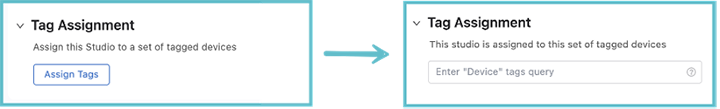
When using any Studio, except for Inventory and Topology, it is important to remember that you need to assign User Tags to the Studio. These tags relate to devices commissioned with the Inventory and Topology Studio. Only devices tagged to a Studio will be affected by any proposed configuration.
When you open up any Studio, other than Inventory and Topology, you will see the tag assignment option. Click Assign Tags and enter the User Tags for the devices you want the Studio to affect.
This will be the first Studio that you’ll use, because it is responsible for making devices and their interfaces available for configuration in Studios. It serves as a control point for separating or combining your wider network topology with the topology that Studios configures.
With the Inventory and Topology Studio, you can accept devices and interface changes in your wider network topology and incorporate those devices and changes into Studios configuration. You can also use it to manually add devices and configure their interfaces for use in Studios.
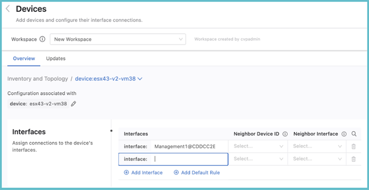
When you click on Inventory and Topology, the Inventory and Topology page is displayed.
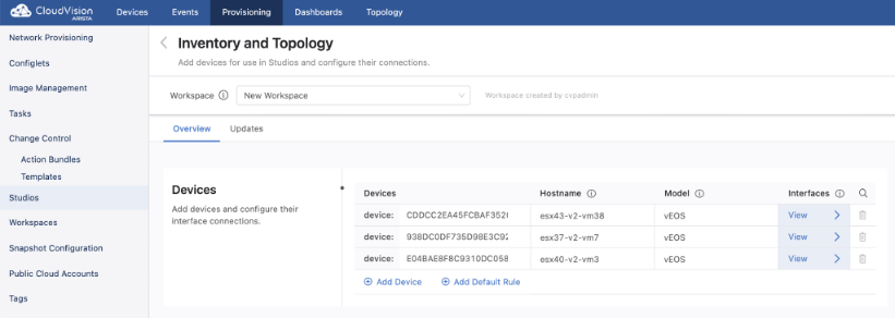
From the Inventory and Topology page you can add devices and then configure their interfaces. Any device added here will be made available for use in other Studios. Once the information for each device has been entered, click View. This will display the Devices page, which shows the interfaces on a selected device.From this page you can add device interfaces and configure their connections to other device interfaces
Select the Updates tab, to view new devices and amendments to device connections in your network. You can quickly add any device or interface changes in your network by using Updates.
All updates and their type will be listed here, and you can choose to accept these updates or ignore them. Accepting adds devices and their interfaces for use in Studios and updates any configuration in Studios the device relates to. Ignoring the updates will omit them from being configured in any Studio.
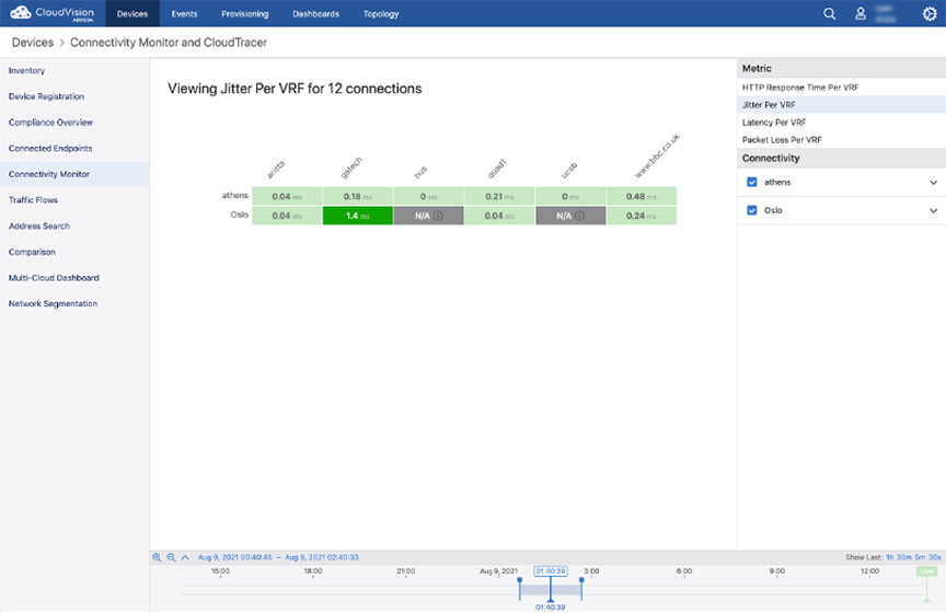
The Connectivity Monitor Studio configures an EOS feature to send probes to a remote host. EOS will then report latency, jitter, round-trip times, and HTTP connectivity to those remote hosts. The corresponding telemetry for the monitored hosts can be found under Devices and Dashboards.
With Connectivity Monitor, you can set up or update the hosts and set which hosts should be monitored.
Select the Connectivity Monitor Studio to display the following screen.
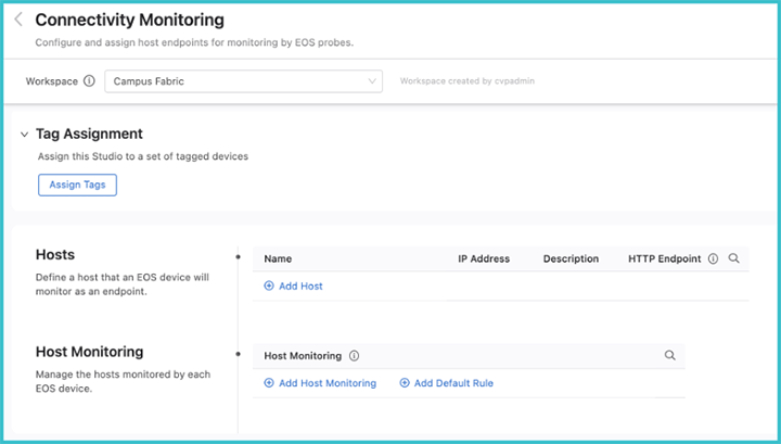
From the Connectivity Monitorscreen, the hosts that the probes will monitor can be defined. Enter a name for the device followed by the IP address and a description for the host. Enter an optional HTTP URL, which will configure the EOS to measure the HTTP response time for that URL.
Groups of devices can be defined for monitoring by an EOS probe using Host Monitoring. Use device tags to define the host groups.
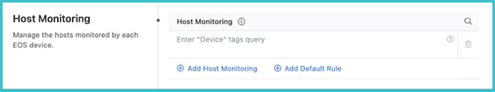
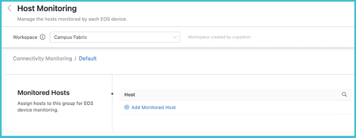
After one or more device tags have been defined, click on the arrow to the right. This will allow you to add hosts to the tagged group for monitoring. These hosts must already have been defined in the previous Hosts section.
After the Studio has been configured, review the Workspace and submit to Change Control. Once it has been approved, the results of the configured monitoring can be viewed by selecting the Connectivity Monitor under Devices.
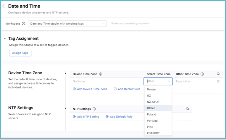
The Date and Time Studio is used to set the device time zones and to assign devices to NTP servers.
You can assign time zones to a set of tagged devices, and set a default time zone that is applied to all assigned devices not specified with a device tag query.
To set a time zone, click Add Device Time Zone or Add Default Rule. If relevant, enter a device tag, and then select a time zone from the drop down menu.
Time zones are ordered alphabetically. If the desired time zone is not in the list, select Other and enter a name for that time zone in the Other Time Zone field.
Once you have assigned time zones to devices and optionally set the default time zone, review and submit the Workspace. Once it is approved and executed in Change Control, the new settings will come into effect on your network.
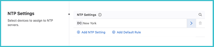
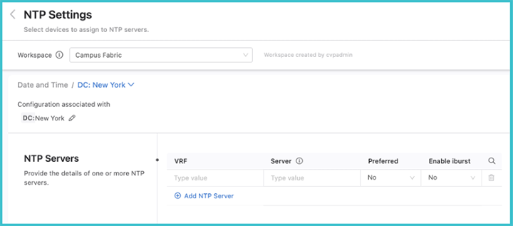
You can assign devices to an NTP server using device tags. Click Add NTP Setting and then enter a device tag to select devices with that tag. When done, click the arrow on the right.
Add NTP servers for these tagged devices by clicking Add NTP Server. Multiple servers can be added for the selected device tag, but only one server should be set as preferred. You can also enable iburst, which will send eight packets to the NTP server on start-up instead of a single packet. This will allow for faster synchronization.
When you have assigned NTP servers to all the device tags, review and submit the Workspace. Once it is approved and executed in Change Control, the NTP settings will come into effect on your network.
The Interface Configuration Studio is used to provision interfaces that have been defined elsewhere. With it, you can configure interface speed, switchport mode, access VLAN or tagged VLANs, and enable or disable the interface. You can set up profiles with configurations for these attributes, which can then be applied to multiple interfaces. The use of profiles means that you do not need to separately configure repeating attributes for each device.
Select Interface Configuration to display the following screen.
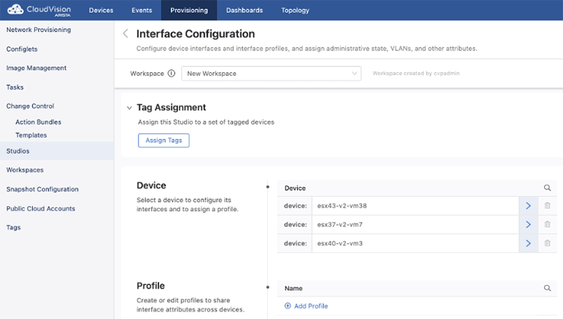
You can either configure an interface belonging to an individual device, or you can configure an interface profile.
All devices that have been commissioned for Studios using Inventory and Topology Studio will be listed under Device. Select the device to configure one or more interfaces for by clicking the arrow on the right.
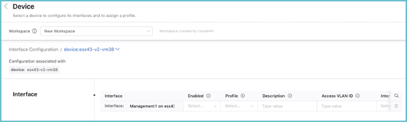
The list of interfaces that can be configured on this device and the available options are displayed.Scroll to the right to see all of the available options.
There is also a profile option, which can be used to assign a profile to the device. If you assign a profile, you do not need to enter a value for any other inputs; any values that you do enter for other inputs will override the values of the profile.
Profiles are used to avoid having to configure each device interface separately. You can create profiles with different characteristics and then assign a single profile to a device interface, which will apply the configuration associated with that profile to the interface of the device.
On the homescreen of Interface Configuration, click Add Profile. Enter a profile name and click the arrow on the right. The following screen is displayed.
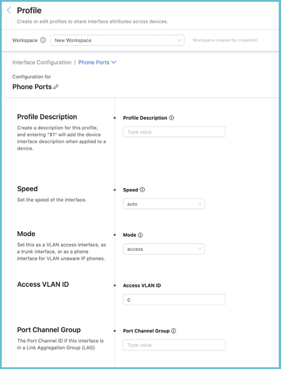
From the Profile screen, the speed, the switchport mode, the VLAN access, or tagged VLANs can be set. The modeselected for the interface may present you with more input options. When entering a description for the profile, enter “$1” which will pull the individual interface’s description into the description when applied to a device. For instance, you could give the profile description “Floor 3 phone ports: $1”; when you apply this profile to a device interface with the description “Office 1”, the full description of the interface will then be read elsewhere as: “Floor 3 Phone Ports: Office 1”.
When the profile has been configured, apply it to device interfaces by selecting a device to configure. The profile can be applied to multiple interfaces across multiple devices. If you enter any individual interface parameters with a profile selected, the individual parameters will override those of the profile.
The Streaming Telemetry Agent Studio enables you to define the streaming telemetry agent (TerminAttr) configuration for EOS devices streaming to CloudVision. The streaming telemetry agent is integral to the communication of state between network devices and CloudVision.
When you open the Studio, the following screen will be displayed.
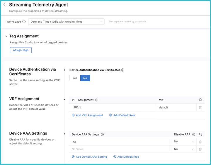
If you select No, the ingest key will be used, which is a shared cleartext key. This key is defined as part of the CloudVision set up process.
By selecting Yes, certificates are used for streaming authentication. CloudVision generates a JSON Web Token (JWT) that is then saved to a temporary location (e.g. /tmp/token). This token is used by TerminAttr for the initial secure authentication, and once authentication is successful, TerminAttr generates a certificate signing request (CSR) and sends it to the CloudVision server, which then signs the CSR with its own CA certificate and provides the generated client certificate to TerminAttr and stores it in the certificate partition on EOS. After this, TerminAttr will switch to using the client certificate and key, and renames the token by appending .backup to the filename and will not use it anymore.
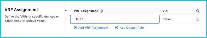
Once you have selected the mode for authenticating the data, the VRF assignment can be selected. Here you will select devices with a tag query and then assign them to a VRF.
You can select devices using a tag query and disable elements of AAA for them.
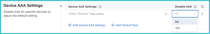
When disabling AAA, you are disabling authorization and accounting for eAPI commands sent by CloudVision to TerminAttr only when the Advanced Login setting is used. This does not affect AAA for other transports, such as SSH or eAPI over HTTPS.
The Advanced Login setting has been the default login method since version 2021.2.0. It can use multi-factor authentication and one-time passcodes to authenticate all CloudVision managed devices when you authenticate with CloudVision. When you select Yes, all eAPI requests are sent over the gRPC session established by TerminAttr instead of eAPI over HTTPS.
Disabling AAA is required in situations when the Advanced login setting is enabled and users are authenticated with certain RADIUS servers, where the server does not support authorization requests that do not have a preceding authentication request.
The Streaming Telemetry Agent studio allows you to enable streaming to multiple clusters. In addition, you can configure a number of flags, including OpenConfig streaming. Devices stream state to CloudVision by using a streaming agent, TerminAttr. When a device is onboarded to a cluster, the streaming agent is automatically enabled to stream telemetry data. This studio allows you to further configure the agent and to set up streaming to other clusters.
Streaming to other clusters is limited to telemetry data and will not share configuration in Provisioning between clusters. You can select devices by tags and assign them to a cluster to stream data. There is no limit on the number of clusters a device can stream data to. Before streaming to other clusters, the secure onboarding token from each cluster must be copied to devices.
When you want to create a warm backup cluster with telemetry data, you will enable devices to stream to one or more other clusters.You will also enable it when you want to make device telemetry data available to other users of a cluster.
You have the ability to define which devices stream data to another cluster using tags, which will enable only a selection of devices in this cluster to stream data to another cluster. Before enabling multiple cluster streaming, you must copy the secure onboarding token from the other clusters and paste onto the affected devices. This token can be found in Onboard with Certificates under Device Onboarding.
/Enable%20Multiple%20Clusters.png)
/Create%20a%20cluster%20profile.png)
/Add%20Devices%20to%20Stream.png)
Devices are identified with tags. If you want to provide a back-up cluster with all streaming data, use the device:* or create and use a tag that identifies a group of devices.
/Assign%20Cluster%20Profile.png)
Assigning a cluster profile identifies the cluster that devices will stream state to.There is no limit to the number of clusters a device can stream to.
When the workspace is submitted and the associated change control executed, the devices will begin streaming to multiple clusters.
Custom Flags allows you to assign streaming agent configuration to sets of devices. This allows you to assign proxy addressing, ECO DHCP collection, the streaming agent interface, OpenConfig streaming, and other configurations.
Configuration is assigned to sets of devices using tags. The device:* tag will assign configuration to all devices in this cluster. If devices are on different VRFs or the streaming agent used different interfaces, you should use or create and use a tag that identifies a subset of devices sharing these properties.
/Create%20a%20tag.png)
Submitting the workspace and executing the associated change control will push this configuration to devices.
The Campus Fabric Studio provides a single point of control over the configuration of a campus network. The Studio is designed to allow the user to deploy and manage campus devices within the network using design patterns consistent with Arista best practices.
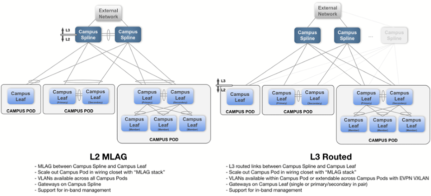
The Studio supports two common campus fabric designs. These designs are illustrated below, with support in beta-version for the L2 MLAG fabric.
For more information, refer to Deploying and Configuring a Campus.
Select Campus Fabric to display the Campus Fabric screen.
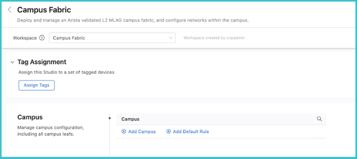
To create a new campus, click Add Campus and enter a name for the campus network. When done, click the arrow on the right.
The main configuration screen for the campus will be displayed.
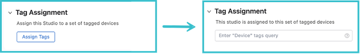
To assign devices that belong to this campus,cick the dropdown arrow beside Tag Assignment and click Assign Tags. You can now add devices with a tag query to this campus network. If a desired device is not present, add it using the Inventory and Topology Studio or, if the tag is not present, create a new User Tag.
Next, configure the parameters and aspects of the L2 MLAG fabric. These parameters are used throughout the campus network when an MLAG pair exists. Configure the VLANs that will be defined for the campus network. A special management network may be defined when in-band management of the switches is required. The SVI virtual address is used as the anycast gateway across the campus Spline switches, as well as an IP helper address for DHCP relay functionality.
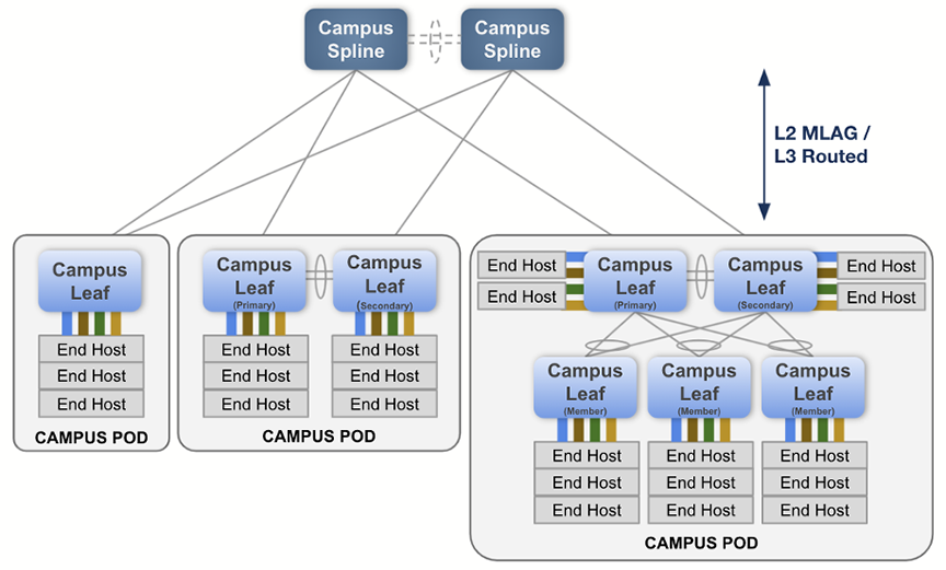
Central to the configuration of a campus network is assigning the roles to the selected devices in its fabric. They can be either campus Spline devices or leaf devices within a pod.
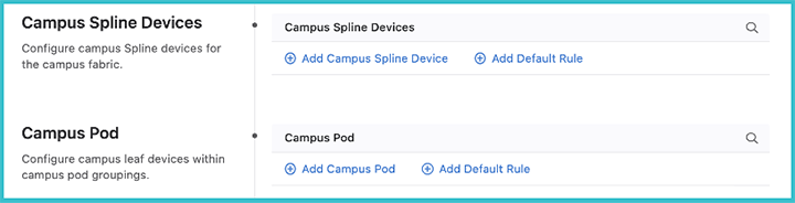
A campus Spline device may be used for both connecting downstream campus leaf switches, as well as connecting hosts. The campus Spline device will often have links toward networks external to the campus fabric.
A pod is a collection of leaf devices that connect to a campus Spline pair of switches. Each pod consists of one or more switches and may be used to form an MLAG stack. Some examples of campus pods are shown below:
The selection of devices available to assign either as campus Splines or as members of a pod are those that you defined earlier on this screen as belonging to the campus.
The connections between devices are configured in the Inventory and Topology Studio. If the devices are already wired-up in your network, they will be shown there. If not, the intended connections can be specified in that Studio, and configuration for those interfaces will be generated.
Once the configurations of your campus fabric have been set, submit the Workspace and your campus network will be available for review and approval in Change Control.
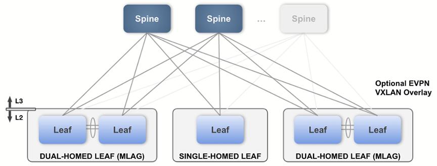
You’ll use this Studio along with EVPN Services to build a layer 3 leaf-spine network. The L3 Leaf-Spine Studio configures Day 1 deployment of the network, and EVPN Services configures Day 2 operations.
The Studio has been designed to support the following Arista validated L3 leaf-spine design:
The following device tags must be in place before configuring the inputs in this Studio. You can create these tags within the same Workspace by accessing Tags.
| Tag | Example | Description |
|---|---|---|
| DC | DC: DC1 | DC defines the data center that is being configured. |
| DC-Pod | DC-Pod: DC1 | Data center pod name. |
| Role |
Role: Leaf Role: Spine |
Device Role. Can either be a leaf or spine. |
| Spine-Number | Spine-Number: 1 |
The number for a spine device.Each spine must have a unique number. |
| Leaf-Domain | Leaf-Domain: 1 |
Specifies the leafs within a common AS, which is usually an MLAG pair of leafs.The value must be an integer. |
| Leaf-Number | Leaf-Number: 1 |
The number for a leaf device.Each leaf must have a unique number. Leaf pairs are assumed to be numbered consecutively starting with an odd number (e.g. the device tagged Leaf-Number:9 and the device tagged Leaf-Number:10 are two devices in an MLAG pair of leafs). If a leaf is not part of an MLAG pair, just use one number of the odd-even pair and do not use the other number for another leaf (e.g. the device tagged Leaf-Number:1 will be configured as a standalone leaf if no other device is tagged Leaf-Number:2). |
The tag placement is illustrated in the following diagram:

Once tags are in place, you can create a data center in the Studio using the Data Center (DC) tag.
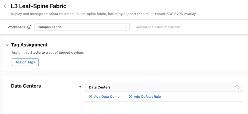
After a data center is in place, then create and configure its pods. Each pod is a leaf-spine module inside the data center fabric. Use the DC-Pod tag to assign devices to a pod.
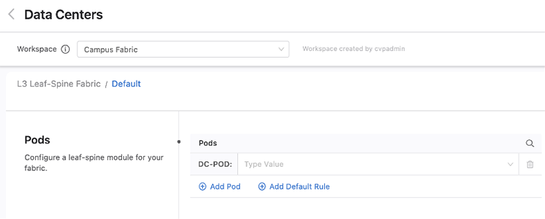
Next,you will be presented with pre-filled values for the fabric of this pod, along with sections that allow you to add leaf and spine devices. Change the fabric configuration for the pod as needed.
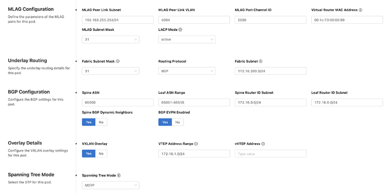
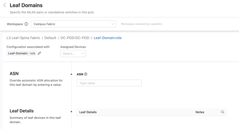
You can add spine and leaf devices by using the Role tag. When adding a leaf device, you can further specify an ASN that will override the ASN number set at the pod level. You’ll also be able to see on this screen a summary of all the devices in this domain.
Once you have configured all the data centers, pods, and their devices, review and submit the Workspace. A change control containing the configuration updates associated with the changes from the Workspace will be created. Review, approve, and execute the change control for the fabric configuration defined in the Workspace to take effect in the network.
The EVPN Services Studio allows you to deploy L2 and L3 network services. These services are applied to tenants that you create. Each tenant shares a common Virtual Network Identifier (VNI) range for MAC-VRF assignment.
The following tags are required for this Studio. They will already be in place if you have deployed an L3 leaf-spine fabric with the Layer 3 Leaf-Spine Fabric Studio.
| Tag | Example | Description |
|---|---|---|
| router_bgp.as | router_bgp.as:65050 | Defines the BGP ASN that the switch will use when configuring overlay VRFs, VLANs, and VLAN aware bundles. |
| router_bgp.router_id | router_bgp.router_id:172.16.0.1 | Defines the BGP Router ID used on the switch and makes up part of the route-distinguisher and route-target fields. |
| mlag_configuration.peer_link | mlag_configuration.peer_link:Port-Channel2000 |
Specifies the MLAG peer link used on a switch that has
an MLAG peer.
Note: This tag is only necessary for MLAG peer
relevant configuration. |
| Leaf-Domain | Leaf-Domain:1 | Specifies the leafs within a common AS, which are usually an MLAG
pair of Leafs. The value must be an integer. Note: This tag is only necessary for MLAG peer relevant
configuration.
|
| Leaf-Number | Leaf-Number:1 |
For a leaf device, its number. Each leaf must have a unique number. Leaf pairs are assumed to be numbered consecutively starting with an odd number (e.g. the device tagged Leaf-Number:9 and the device tagged Leaf-Number:10 are two devices in an MLAG pair of leafs). If a leaf is not part of an MLAG pair, just use one number of the odd-even pair and don’t use the other number for another leaf (e.g. the device tagged Leaf-Number:1 will be configured as a standalone leaf if no other device is tagged Leaf-Number:2). Note: This tag is only necessary for MLAG peer relevant
configuration.
|
When you open EVPN Services, the following screen will be displayed.From this screen, tenants are created and the default VRF and MAC-VRF attributes for all tenants are created.
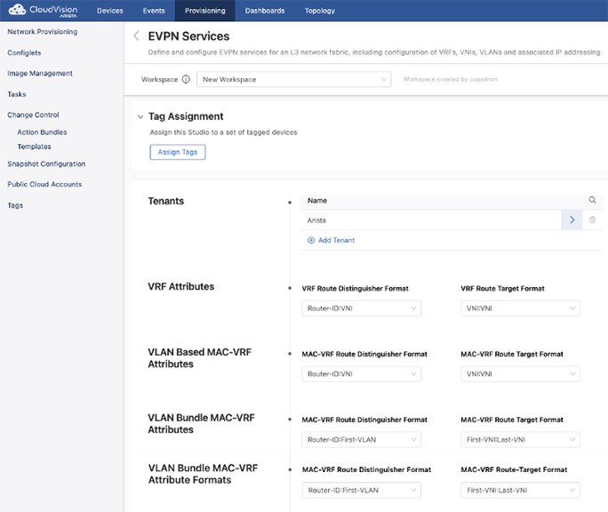
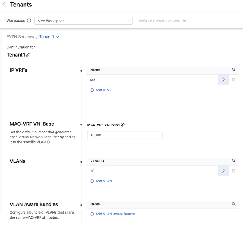
When creating a tenant or selecting an existing tenant to configure, you can create VRFs and VLANs for use within this tenant. You will also determine the base number used to generate VNIs.
When configuring a VRF, always specify a VNI. The remaining fields are all optional and their use depends upon how you are configuring your network.
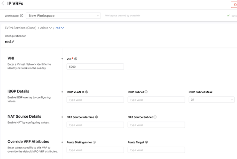
The iBGP Detail fields are necessary when a VTEP is composed of a pair of leaf switches that have a host (or hosts) connected to only one switch in an MLAG pair. If incoming traffic arrives at the leaf switch in the pair that the host is not connected to, the leaf switch will drop that packet. By configuring a VLAN and SVI to establish an IBGP peering on for this VRF, both switches in an MLAG pair are aware of all host connections including those connected to only one switch.
NAT Source Details are used to configure a virtual source NAT address for the VRF. It is used mainly for troubleshooting, because all VTEPs share the same IP address and MAC address for each SVI. This means that pings to workloads behind remote VTEPs or local workloads (e.g. MLAG VTEPs) may not be successful because the reply cannot be returned. When the destination host responds to either an ARP request or ICMP echo request, the reply is processed by the first VTEP it arrives at, which is because all VTEPs have the same IP and MAC address. In order for each VTEP to successfully ping a workload, configuring a NAT source address enables a dedicated loopback interface that can be used as the source address for pings within a VRF.
The Override VRF Attributes section allows you to override the default VRF attributes associated with this VRF.
A name must be provided for each VLANthat is created.Then select whether it is applied to a routed or bridged setting.
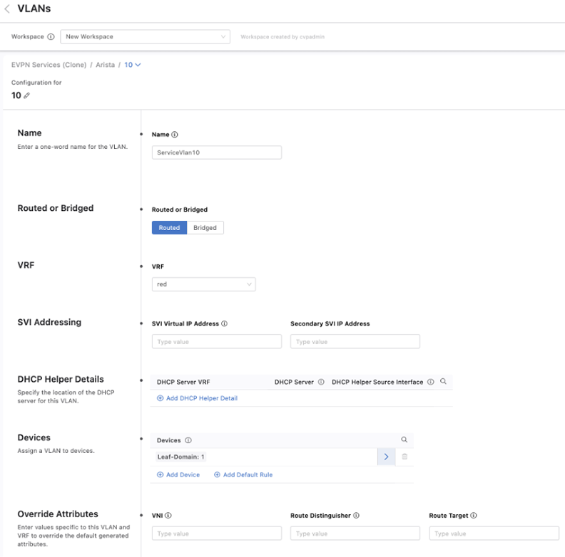
By default, the toggle is set to routed. You can also provide details of a DHCP server and provide a default gateway by entering a Switched Virtual Interface (SVI) virtual IP address, which are options only available with a routed VLAN.
The last two options, Devices and Override Attributes, are shared with a bridged VLAN, where devices can be assigned to this VLAN and override the default values generated for configuration elements associated with this VLAN.
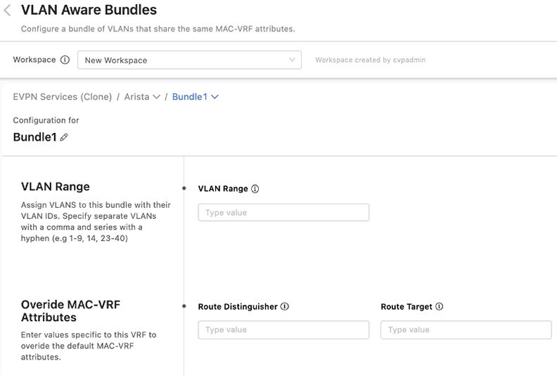
You can bundle VLANs that have already been created within a tenant into VLAN aware bundles. Each bundle consists of a range of VLANs that share the same MAC-VRF attributes, which you can define by overriding the default MAC-VRF attributes shared across tenants.
The Segment Security Studio enables you to separate your network into logical domains. Each domain contains a set of segments and policies that determine the forwarding behavior between segments. A segment describes a set of endpoints with identical security policies and network access privileges.
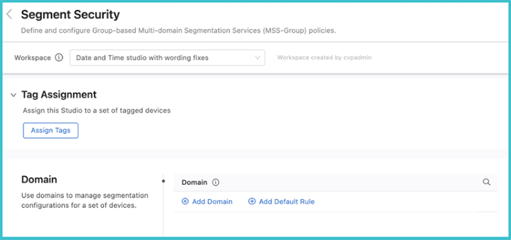
To create a segmentation domain, click Add Domain and enter a device tag query. A segmentation domain is identified by device tags, which gives you the ability to select a group of switches that form the domain. All devices in the same domain will be configured with identical segmentation policies.
Once you have created the domain, click the arrow on the right, and the Policies screen will be displayed.
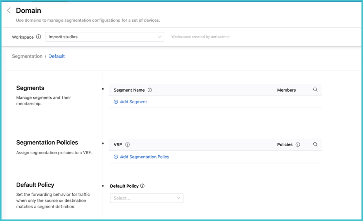
Enter a segment a name and identify its members. The segment membership is based upon either IPv4 or IPv6 prefixes, or both.
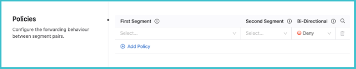
Next, set the security policies between segments. These policies apply to a single VRF. Configure segment policies for the VRF by clicking View underneath the Policies heading. Determine the relationship between pairs of segments inside the domain and the forwarding behavior of traffic between them.
Using Forescout, an MSS-G configuration can be pushed automatically to CloudVision. This section covers the use of Forescout eyeSegment for policy definition and eyeSight for segment assignment. These systems produce an MSS-G configuration that is dynamic, and while visible on CloudVision, it bypasses the CLI on switches and will therefore not show up in the device running config.
Both integration points are described below. Before deploying this integration, note that there is a terminology overlap:
To configure MSS-G with Dynamic Configuration from Forescout the system must meet the following requirements:
On the Forescout side:
Note the following limitations before configuring MSS-G with Dynamic Configuration from Forescout.
Forescout’s Arista MSS-G module adds the ability to connect to CloudVision and also assigns MSS-G segment ID in the policy manager.
The MSS-G module is an *.fpi file just like any other Forescout module.
/Forescout%20MSS-G%20module.png)
Once installed, double-click on the Arista MSS-G module from the list and enter the CloudVision information:
/Forescout%20-%20Arista%20MSS-G%20Plug-in.png)
The Forescout Policy Manager can be used to assign a user/host/device to an Arista MSS-G segment. This function is available as an action inside any Forescout policy. The conditions for classifying an endpoint to a group within the Forescout policy manager can be advanced combinations of many pieces of data, including DHCP vendor class, DNS event, SNMP system uptime, OS version, Active Directory group, and many other factors. In the example below, other policies (not shown) have classified cameras into the “IOT-Camera'' Forescout group.
In the following example, another policy is defined that assigns the Arista Segment ID of “IOT-Camera” to all the members of the Forescout “IOT-Camera” group. Note that although the example shows a matching Forescout group and Arista MSS-G segment name, this is not required. However, if groups are defined on Forescout and segment policies are defined on CloudVision, then it is mandatory to have matching names.
/Forescout%20-%20Policy%20screen.png)
The Forescout eyeSegment interface can be used to define Arista MSS-G Segment policies. The Zones listed in each eyeSegment policy must match with Arista MSS-G group names being used by Forescout Policy Manager or CloudVision to map IP addresses to groups. Forescout eyeSegment policies that are to be exported to CloudVision must use “All” in the services field.
/Forescout%20-%20eyesegment%20Policy.png)
Select Export to Arista MSS-G to export eyeSegment policies into CloudVision. Check that the appropriate segment-policies show up in CloudVision’s network-wide Network Segmentation view. All Forescout eyeSegment policies must be exported at the same time. If a subset of policies is exported, previously exported eyeSegment policies not currently selected will be removed.
On participating, segmentation-enabled Arista devices, enable OpenConfig with the following commands:
>en
#conf
(config)#management api gnmi
(config-mgmt-api-gnmi)#transport grpc default
(config-gnmi-transport-default)#no shutdown
Add the flag -cvconfig=true to the TerminAttr configuration on each
participating switch:
(config)#daemon TerminAttr
(config-daemon-TerminAttr)#exec /usr/bin/TerminAttr -ingestgrpcurl=<address>:<port> -cvcompression=gzip -ingestauth=token,/tmp/token … -cvconfig=true
(config-daemon-TerminAttr)#no shut
You may add a segmentation configuration via both CVP Studios and Forescout, if desired. However, the configuration should be non-overlapping.
One use-case is defining default policies. Forescout allows you to associate known hosts with segments, and will push segment-policies to CloudVision. However, it does not provide you a way to describe the desired forwarding behavior for unknown hosts. This may be important if, for example, you want to define the desired forwarding behavior between known hosts in the network and the Internet. In this case, you may define a segment with an IP prefix that captures the desired set of unknown hosts (possibly 0.0.0.0/0) and specify segment-policies between this default segment and other defined segments.
ISE/MSS-G integration uses TrustSec data from Cisco ISE to create an MSS-G configuration to distribute to switches via CloudVision. The integration is implemented by an ISE provider that runs in the third-party collector. It maps TrustSec Security Groups (SGTs), Access Control Lists, and policies into MSS-Segments and policies.The integration is built on top of Cisco ISE’s External RESTful Services (ERS) and pxGrid APIs. Most of the integration is based on pxGrid and some information that is not available through pxGrid is loaded using the ERS REST APIs.
The integration requires a few configurations in Cisco ISE. Refer to Cisco ISE documentation for configuration information.
The ISE collector uses pxGrid as part of the integration with Cisco ISE. Client certificates are necessary to communicate with pxGrid. The certificates can be generated in the Cisco ISE web interface.
Verifying pxGrid is enabled in ISE:
For information and instructions to generate certificates, refer to the official Cisco ISE documentation.
Before the ISE collector can be configured, it must be onboarded and enabled.
From the Onboarding interface.
Complete the form and select Onboard.
Cisco ISE Cert File: Upload the file COMMON_NAME_.cer
Cisco ISE Key File: Upload the file client.key (decrypted)
Cisco ISE CA File: Upload chain.cer
pxGrid Port: Leave the default value (8910) or provide the port configured in ISE.
pxGrid User: arista-ise-integration
ERS Username: user_with_ers_permission
ERS Password: password_for_user_above
Upon successful onboarding, the collector client will appear in the Cisco ISE user interface.
From Administration navigate to pxGrid Services and select All Clients.
Find the username in the table.
Check the relevant row.
Click Approve at the top of the table.
Allow up to one minute for the collector to notice the approval.
Data will start streaming to CloudVision. This may be checked in the telemetry browser in CloudVision:
Dataset: analytics
Path: /yang/arista/segmentation/config/domain
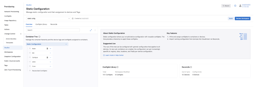
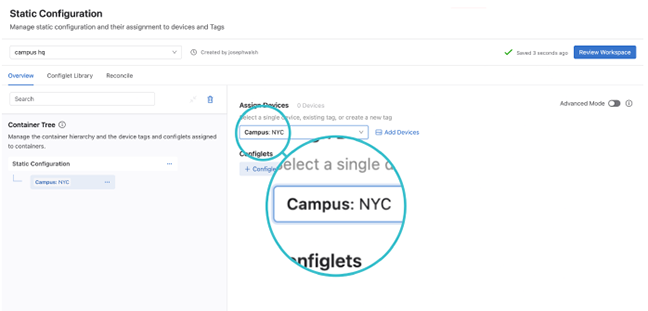
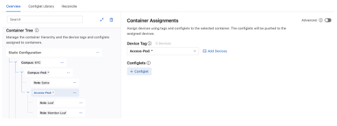
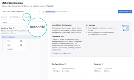
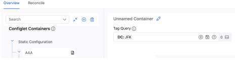
The Static Configuration Studio is used to manage static configuration for devices, provide configuration not created by any other studio, and reconcile differences between a CloudVision designed configuration and the running configuration on a device. Devices are assigned to containers using tags that can identify one or more devices by hostname, role, or location in the network. Each container has configlets of EOS configuration, which are pushed to the EOS devices.
A configlet contains EOS commands that are written by a user. Within a workspace, configlets are assigned to devices in the studio. Once configlets are assigned to devices, the workspace is submitted, and a change control operation is created. When that operation has been reviewed and approved, the configlets are pushed to the running configuration of each assigned device.
Reconciling a device brings the designed config on CloudVision into sync with the running config on the device. Configuration can be out of sync if a device is, for instance, configured via CLI and any designed config in a workspace on CloudVision will not include the update to the device’s running configuration (running config).
A container is assigned configlets. Each container is also assigned a device tag, which associates the container with all devices possessing that tag. When the change control associated with the workspace changes in this studio is executed, the configuration is pushed to devices.
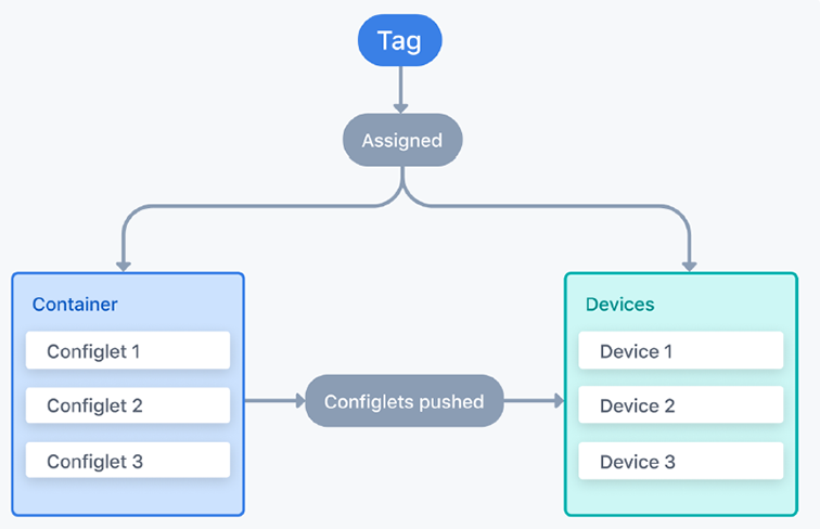
The use of tags to associate a container’s configlets with devices means that a device can be associated with multiple containers. This is because a device can have more than one tag and its different tags can be assigned to many containers.
The following diagram shows two tags assigned to two separate containers. The configlets in both containers will be pushed to Device B because that device is assigned both tags; the other devices will only receive one container’s configlets.
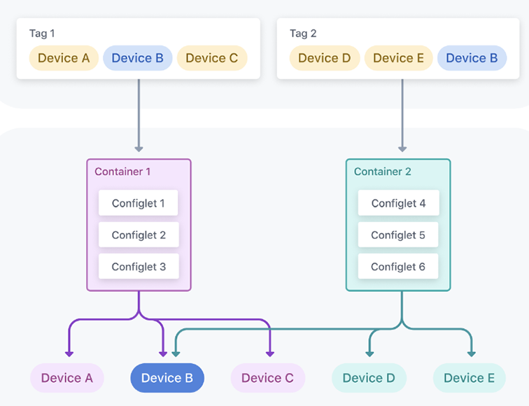
The tags used in the Static Configuration Studio are user tags assigned to devices. A user tag identifies one or more devices, and the tag is assigned to a container.
There are some built in tags like device: *, which identifies all devices registered to studios; or device: <hostname>, which identifies a single device. You can also create your own custom tags in Tags and assign devices to them.
Typically, you will use the tags created in other studios. For example, the Campus Fabric (L2/L3/EVPN) Studio creates a Campus: <campusName> tag for each network. If a network called HQ is created, all devices in that network will have the tag Campus: HQ. You can assign all devices in that network to a container using the Campus: HQ tag. Similarly, you could use the Campus-Pod or Access-Pod tags to target specific campus pod and access pod devices.
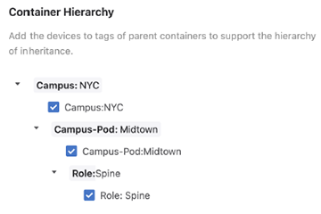
The Hierarchy section explains how you can use the container hierarchy to further refine which device tags are targeted, such as a specific campus pod in Campus: HQ.
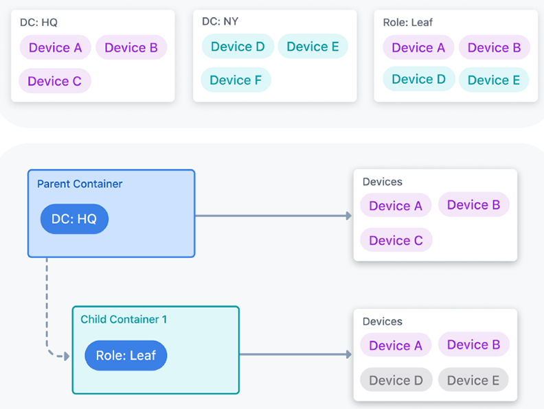
Containers are arranged in a tree-like hierarchy of parent and child containers that control device rules of inheritance. Devices in containers lower down in the tree must have the tags of all parent containers higher in the tree in order for configlets to be pushed to them.
The following image shows a simple tree-like structure of containers relating to two data centers. Devices must be assigned any parent container tags for a container’s configlets to be pushed to them.
A more complex example shows a data center where specific configlets are pushed to devices depending on the pod they belong to. Another container stands outside the DC:HQ hierarchy, which contains configlets pushed to all devices regardless of what pod or data center they belong to.
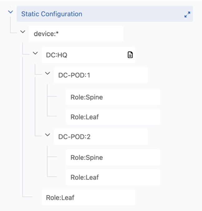
The hierarchy can be understood as follows:
device:* applies to all devices registered to Studios
DC:HQ applies to all devices only with this tag
DC-POD:1 applies only to devices that have this tag and the DC:HQ tag.
While spine devices in both DC-POD:1 and DC-POD:2 have the same Role:Spine tag, the hierarchical structure means that only configlets within either Role:Spine container will be pushed to devices with the parent container tag. Therefore, devices with the tag DC-POD:1 will only receive configlets from the Role:Spine container under the DC-POD:1 container, and similarly, for devices with the DC-POD:2 tag.
By contrast, configlets assigned to the last container, Role:Leaf, will be pushed to all leaf devices because the parent container has the tag device:* assigned to it. This way, devices can be associated with multiple containers and hierarchies.
CloudVision uses several configuration sources. To create and maintain a single designed configuration, a hierarchy exists for CloudVision to determine which configuration source is used to compile the designed configuration. This means that where different sources provide overlapping EOS commands, one source takes precedence over another.
This hierarchy can cause you to see missing or unexpected configuration when using Studios or Network Provisioning. You can use Config Sources in the Configuration of a selected device to view the configuration source to help resolve these issues.
CloudVision begins with the lowest-ranked source when creating the designed configuration and will then overwrite that configuration with a higher-ranked source.
The process CloudVision moves through from lowest ranked to highest ranked is:
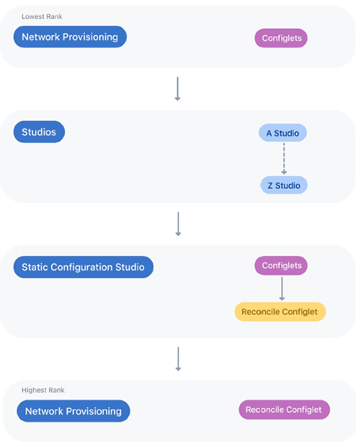
Network Provisioning's reconciled configlets are the highest ranked source. Each source has its own internal ranking, which is explained in further detail below.
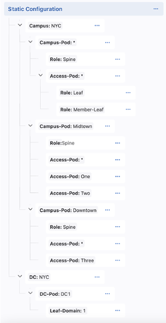
The Static Configuration Studio is preferred to any configuration sources from Network Provisioning and other studios. It has its own internal hierarchy for how configuration is assigned to devices, can be understood in the following example:
Configuration in child containers takes precedence over any parent containers.
The Access-Pod:* container will overwrite any conflicting
configuration supplied by the Campus-Pod:* and
Campus:NYC containers.
For sibling containers, the bottom container in the tree will take precedence
over sibling containers higher in the tree. The Campus-Pod:Downtown
container will overwrite conflicting configuration from the
Campus-Pod:Midtown and Campus-Pod:*
containers.
Understanding the parent-child and sibling precedences together, the
Access-Pod:Three container overwrites conflicting configuration
from all parent containers and their siblings.
When multiple configlets are assigned to a container, the precedence is ordered from left to right. This means that any conflicting configuration between a configlet to the left and configlet to the right is overwritten by the configlet on the right.
You will need to create a new container when you want to associate a configuration with a specific set of tagged devices. Placing containers in a hierarchy allows you to further refine which tagged devices receive configuration assignments, because the hierarchy of containers forms a relation chain based on tags.
Assign a device tag to the container.
The tag acts as a proxy for assigning devices. All devices with the selected tag will have the container’s configlets pushed to their running configuration.
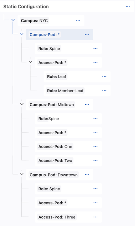
In this example, we have created a hierarchy suited for a small campus, Campus:NYC, designed in the Campus Fabric (L2/L3/EVPN) Studio. It uses the tags created in that studio.
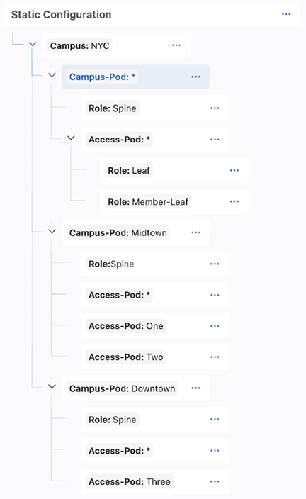
The root level container, Campus:NYC, identifies all devices in that network. Any configlets assigned to this container will be pushed to all devices in that network, because they will all have the Campus:NYC tag.
The Campus-Pod:* container is used for configuration that should be pushed to all devices in any campus pod (i.e. all spines, leafs, and member leafs) in Campus:NYC. The Role:Spine tag within this container will push configuration only to spines in any campus pod. The Access-Pod:* container is used to push configuration to all devices in any access pod and in any campus pod (because the parent container has the tag Campus-Pod:*). The Access-Pod:* child containers, Role:Leaf and Role:Member-Leaf, are used for any leaf device and member leaf device configuration in any access-pod.
The next container branch provides for more specific configuration. Campus-Pod:Midtown is used to apply configuration only to devices with that tags. The child Role:Spine container is used for configuration of spines that are in Campus-Pod:Midtown. The Access-Pod:* applies to all access pods in Campus-Pod:Midtown, and then Access-Pod:One and Access-Pod:Two are used to assign configuration only to devices in those access pods. The same structure is applied to Campus-Pod:Downtown.
In this case, we have added a hierarchy for a small data center connected to the campus. We can apply configlets to the devices associated with each container. The DC:NYC container is a root container at the same level in the tree as the Campus:NYC tag.
Once you have created your hierarchy, you can add configlets to containers.
Devices that already have the tag assigned to a container will have that container’s configuration pushed to them. You will only need to add devices when they do not have the container’s tag or you want to create a device-specific container. A device-specific container is for configlets that only apply to one device.
In most cases, adding a device should only be relevant for device-specific configuration; any new devices configured in another studio will automatically be assigned the tags of that studio.
For example, assigning new devices to an existing leaf domain in the L3 Leaf-Spine Studio will tag those devices with the relevant DC: tag, the DC-Pod tag, and Leaf-Domain tag. However, if you created a new leaf domain, you will need to add a new Leaf-Domain container to your Static Configuration Studio container tree.
Adding a device will assign the device to the tag associated with the container. To add devices to a container:
Ensure that you select the lowest container in the hierarchy that you want configlets to be pushed to devices. The studio will allow you to also tag the device with all parent container tags.
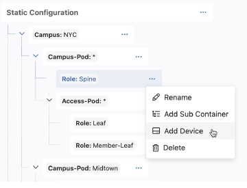
All devices that do not have this tag will be available for selection. You can search by hostname.
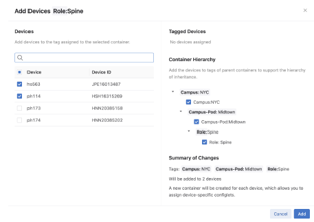
Ensure that all tags are selected. If you do not select all tags, then the device may not form part of the hierarchy’s inheritance model.
Configuration associated with the selected container and any parent containers will be pushed to the devices once the workspace is submitted and its associated change control executed.
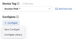
A configlet is a set of EOS commands with a defined scope that form part of the device’s running configuration when pushed to devices. You will define the EOS commands of a configlet in a text editor by creating a new configlet or editing an existing configlet.
If you edit any configlets already assigned to tagged devices, that new configuration will be applied to each assigned device. In this way, configlets provide a way to change the configuration of multiple devices at once.
You will add configlets to containers by either writing a new configlet or selecting one from the Config Library. Any new configlet you create will be added to the configlet library.
Configlets already assigned to the container will be visible as tabs. You can select an existing configlet by clicking this tab and editing the configlet.
Selecting New Configlet will provide a blank textpad to write the EOS commands. Edit the configlet tab to assign a name to the configlet. When completed it will be saved to the Config Library. Selecting a configlet from the Config Library will create a new configlet tab containing the selected configlet. Any edits you make to this configlet will be shared with all other containers to which the configlet is assigned.
Once completed, you can review the workspace and the proposed configuration changes.
All configlets you create in the Static Configuration Studio are stored in the Config Library. This library allows you to view and edit configlets. It also serves as a repository from which you can repeatedly assign configlets to containers.
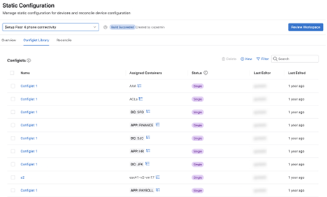
The status of a configlet shows whether it is unused, assigned to a single container, or shared across multiple containers.
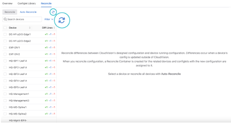
Reconciling is used to resolve differences between the workspace’s designed configuration and the device’s running configuration. This is typically required when a device’s running config has been updated via CLI instead of CloudVision.
Building the workspace will detect if any device configuration is out of sync.
When you reconcile configuration, you will create a new reconcile container with a reconcile configlet that is assigned to all reconciled devices. The reconcile configlet will take precedence over Studio-generated configuration as well as other Static Configlets. If your build fails, and the error message references the reconcile configlet, that may indicate a conflict in configuration precedence. One method to resolve this is to delete the reconcile configlet (or the specific line causing the validation error), rebuild and then reconcile again.
Devices detected with unresolved running configuration will be displayed.
This will update the list of devices out of compliance.
You can choose which lines from the running configuration to include or overwrite the designed configuration by checking or unchecking the checkboxes.
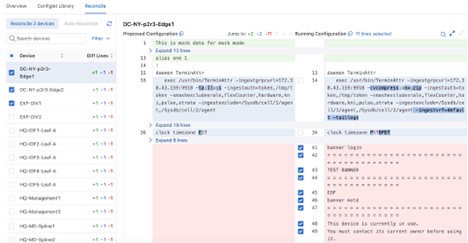
The workspace will rebuild and a new container in the Container Tree called Reconciled Configlets will be created.
When the associated change control is executed, the running configuration and the designed configuration will be synchronised, bringing the running configuration of the device into compliance.
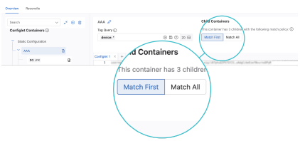
The advanced mode provides additional options for configuring your tree. It introduces the concept of match rules, which affect how the hierarchy assigns configlets to devices. It also allows you to assign multiple tags to a container using tag query.
You can enable advanced mode when viewing a container’s assignments.
Select a container, then click the Advanced Mode toggle.
Related Topics
The container hierarchy can be further customized with match rules. The two rules allow you to define how the devices associated with sibling containers have configlets pushed to them.
The match rules operate in a top-down hierarchy from the parent container. The hierarchy of containers is complemented by match rules. These rules further control how configlets are pushed to child containers.
The match first rule will only push configlets to devices that have not already received configlets from a sibling container.
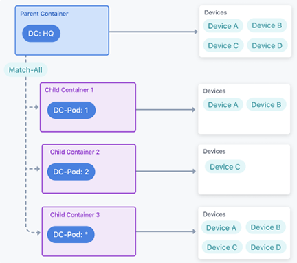
In the following diagram, Device D has the tag DC-Pod: 4. Only Device D receives configlets from Container 3, because all other devices have already received configuration from sibling containers.
The Match All instruction will push configlets to all child devices with matching tags.
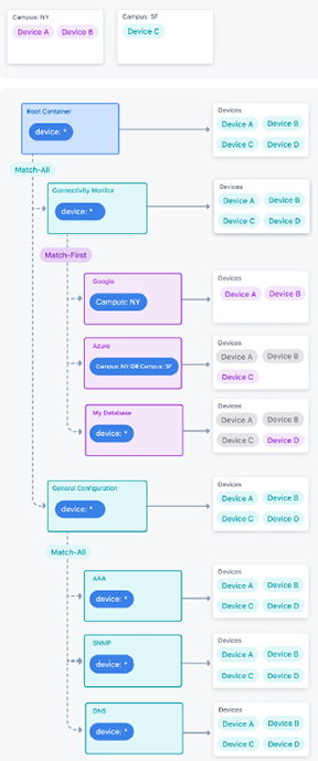
The following example shows the match rules combined with container hierarchy for four devices. There are two campus tags that associate devices with the Google and Azure containers. Match rules allow you to control which configlets are assigned on a per-device level when devices match multiple containers.
Notice how using the Match First Policy allows us to control which configlets are assigned to a device. Device A and B match both the Google and Azure containers due to the Campus: NY tag. But by using the Match First Policy, they do not inherit the configlets in the Azure container because they matched the Google container first. The order of the containers is controlled by the operator, by dragging and dropping them in the Static Configuration Studio UI.
You will create a new container when you want to push configlets to a specific set of devices. These devices are identified by a tag, which is assigned to the container.
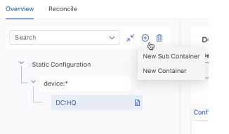
You can add a child container (New Sub Container) or a sibling container (New Container).
If you are adding a child container, set the match rule in the parent container.
The tag associates devices with the container and all configlets created in the container will be pushed to the tagged devices.

When the workspace is submitted, a change-control is created, and when executed the configlets are pushed to devices with the container’s assigned tag.