Built-In Studios
There are currently seven built-in Studios in the beta-version, which each relate to a network feature. You can create your own custom-built Studios by following the Creating a New Studio instructions.
Any devices you wish to include in a Workspace configuration must already have been commissioned by using the Inventory and Topology Studio. Consequently, this is the first Studio that you should use and which enables the use of all other Studios.
When using any Studio, except for Inventory and Topology, it is important to remember that you need to assign User Tags to the Studio. These tags relate to devices commissioned with the Inventory and Topology Studio. Only devices tagged to a Studio will be affected by any proposed configuration.
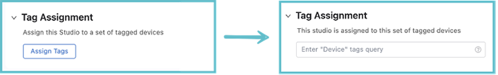
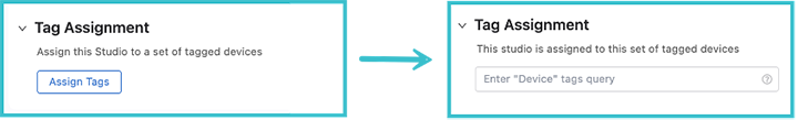
When you open up any Studio, other than Inventory and Topology, you will see the tag assignment option. Click Assign Tags and enter the User Tags for the devices you want the Studio to affect.
Inventory and Topology
This will be the first Studio that you’ll use, because it is responsible for making devices and their interfaces available for configuration in Studios. It serves as a control point for separating or combining your wider network topology with the topology that Studios configures.
With the Inventory and Topology Studio, you can accept devices and interface changes in your wider network topology and incorporate those devices and changes into Studios configuration. You can also use it to manually add devices and configure their interfaces for use in Studios.
Adding a Device and Configuring its Interfaces
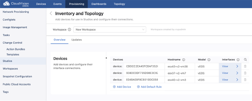
When you click on Inventory and Topology, the Inventory and Topology page is displayed.
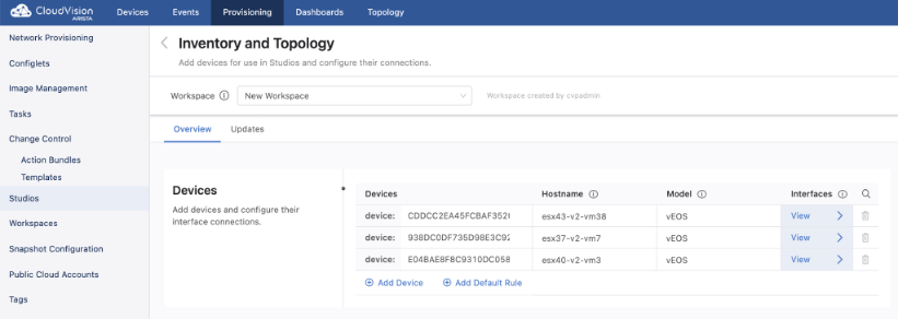
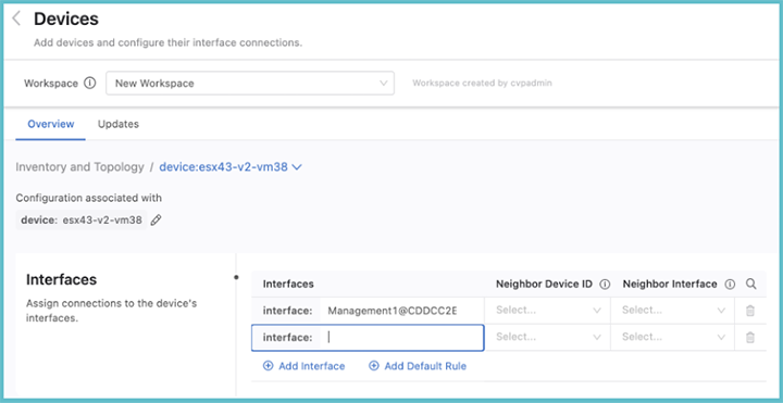
From the Inventory and Topology page you can add devices and then configure their interfaces. Any device added here will be made available for use in other Studios. Once the information for each device has been entered, click View. This will display the Devices page, which shows the interfaces on a selected device.From this page you can add device interfaces and configure their connections to other device interfaces
Managing Updates to the Network Topology
Select the Updates tab, to view new devices and amendments to device connections in your network. You can quickly add any device or interface changes in your network by using Updates.
All updates and their type will be listed here, and you can choose to accept these updates or ignore them. Accepting adds devices and their interfaces for use in Studios and updates any configuration in Studios the device relates to. Ignoring the updates will omit them from being configured in any Studio.
Connectivity Monitor
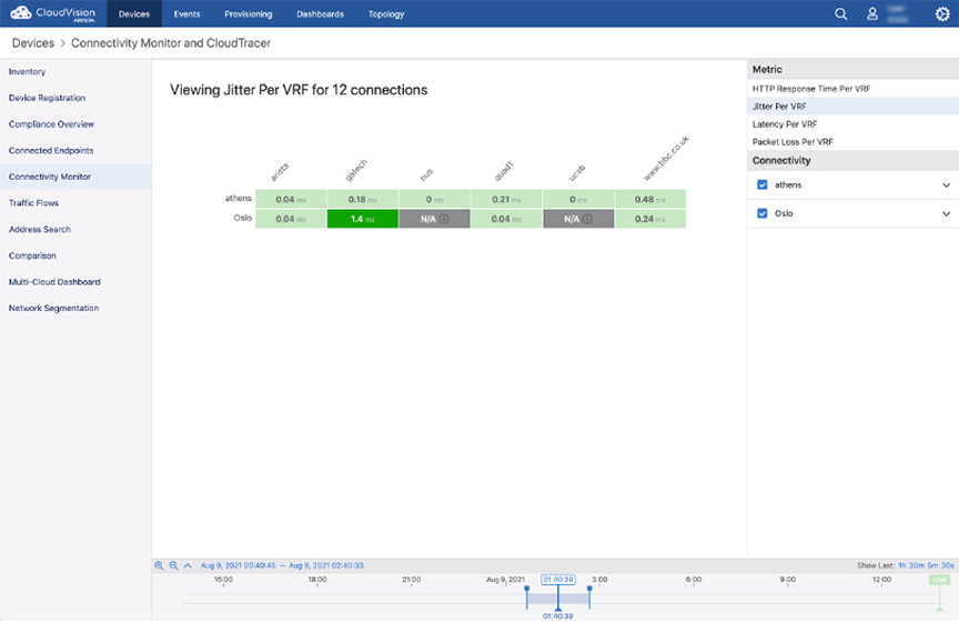
The Connectivity Monitor Studio configures an EOS feature to send probes to a remote host. EOS will then report latency, jitter, round-trip times, and HTTP connectivity to those remote hosts. The corresponding telemetry for the monitored hosts can be found under Devices and Dashboards.
With Connectivity Monitor, you can set up or update the hosts and set which hosts should be monitored.
Select the Connectivity Monitor Studio to display the following screen.
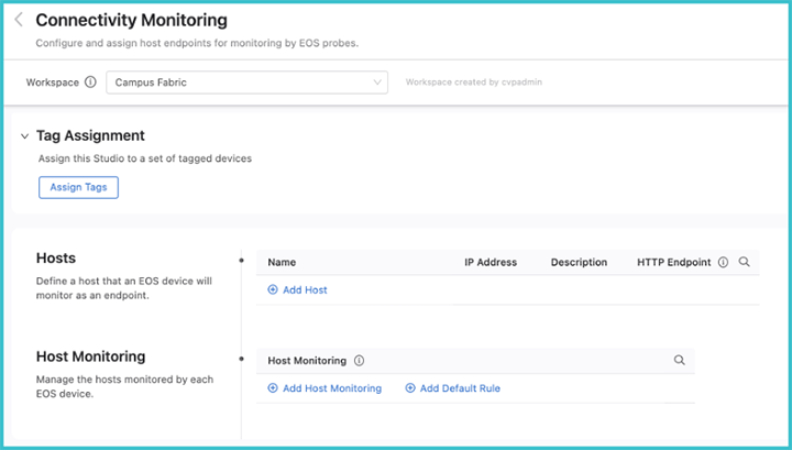
From the Connectivity Monitorscreen, the hosts that the probes will monitor can be defined. Enter a name for the device followed by the IP address and a description for the host. Enter an optional HTTP URL, which will configure the EOS to measure the HTTP response time for that URL.
Groups of devices can be defined for monitoring by an EOS probe using Host Monitoring. Use device tags to define the host groups.
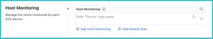
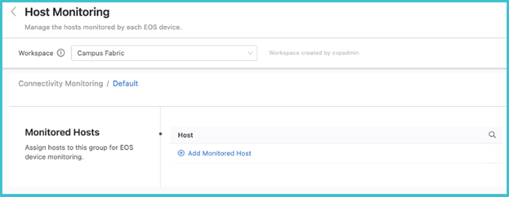
After one or more device tags have been defined, click on the arrow to the right. This will allow you to add hosts to the tagged group for monitoring. These hosts must already have been defined in the previous Hosts section.
After the Studio has been configured, review the Workspace and submit to Change Control. Once it has been approved, the results of the configured monitoring can be viewed by selecting the Connectivity Monitor under Devices.
Date and Time
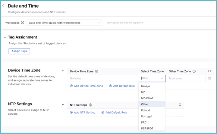
The Date and Time Studio is used to set the device time zones and to assign devices to NTP servers.
Setting a Device Time Zone
You can assign time zones to a set of tagged devices, and set a default time zone that is applied to all assigned devices not specified with a device tag query.
To set a time zone, click Add Device Time Zone or Add Default Rule. If relevant, enter a device tag, and then select a time zone from the drop down menu.
Time zones are ordered alphabetically. If the desired time zone is not in the list, select Other and enter a name for that time zone in the Other Time Zone field.
Once you have assigned time zones to devices and optionally set the default time zone, review and submit the Workspace. Once it is approved and executed in Change Control, the new settings will come into effect on your network.
Configuring the NTP Settings
You can assign devices to an NTP server using device tags. Click Add NTP Setting and then enter a device tag to select devices with that tag. When done, click the arrow on the right.
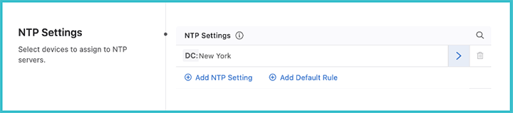
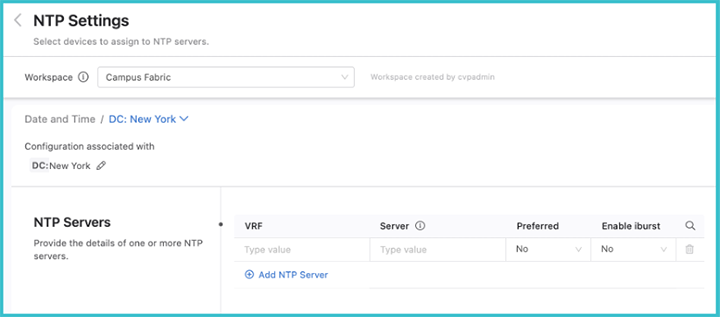
Add NTP servers for these tagged devices by clicking Add NTP Server. Multiple servers can be added for the selected device tag, but only one server should be set as preferred. You can also enable iburst, which will send eight packets to the NTP server on start-up instead of a single packet. This will allow for faster synchronization.
When you have assigned NTP servers to all the device tags, review and submit the Workspace. Once it is approved and executed in Change Control, the NTP settings will come into effect on your network.
Interface Configuration
The Interface Configuration Studio is used to provision interfaces that have been defined elsewhere. With it, you can configure interface speed, switchport mode, access VLAN or tagged VLANs, and enable or disable the interface. You can set up profiles with configurations for these attributes, which can then be applied to multiple interfaces. The use of profiles means that you do not need to separately configure repeating attributes for each device.
Select Interface Configuration to display the following screen.
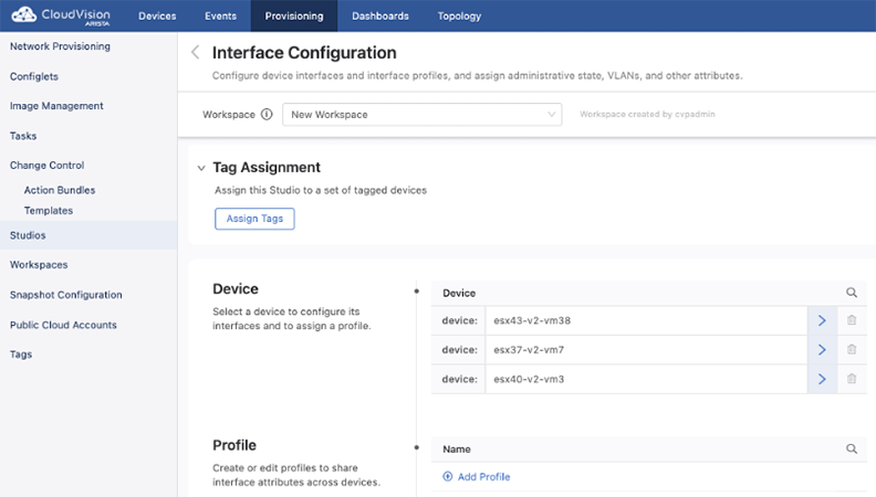
You can either configure an interface belonging to an individual device, or you can configure an interface profile.
Configure a Device
All devices that have been commissioned for Studios using Inventory and Topology Studio will be listed under Device. Select the device to configure one or more interfaces for by clicking the arrow on the right.
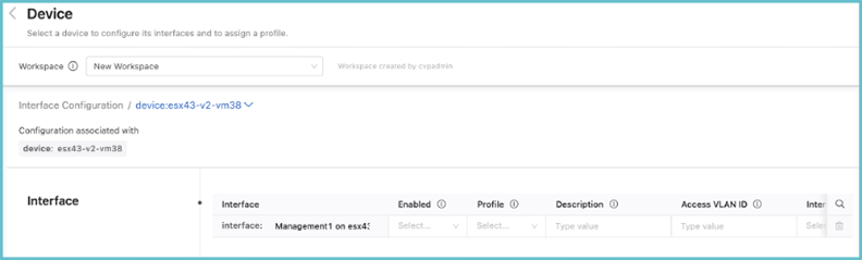
The list of interfaces that can be configured on this device and the available options are displayed.Scroll to the right to see all of the available options.
There is also a profile option, which can be used to assign a profile to the device. If you assign a profile, you do not need to enter a value for any other inputs; any values that you do enter for other inputs will override the values of the profile.
Configuring a Profile
Profiles are used to avoid having to configure each device interface separately. You can create profiles with different characteristics and then assign a single profile to a device interface, which will apply the configuration associated with that profile to the interface of the device.
On the homescreen of Interface Configuration, click Add Profile. Enter a profile name and click the arrow on the right. The following screen is displayed.
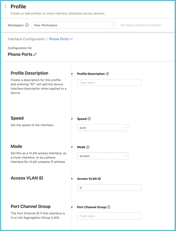
From the Profile screen, the speed, the switchport mode, the VLAN access, or tagged VLANs can be set. The modeselected for the interface may present you with more input options. When entering a description for the profile, enter “$1” which will pull the individual interface’s description into the description when applied to a device. For instance, you could give the profile description “Floor 3 phone ports: $1”; when you apply this profile to a device interface with the description “Office 1”, the full description of the interface will then be read elsewhere as: “Floor 3 Phone Ports: Office 1”.
When the profile has been configured, apply it to device interfaces by selecting a device to configure. The profile can be applied to multiple interfaces across multiple devices. If you enter any individual interface parameters with a profile selected, the individual parameters will override those of the profile.
Streaming Telemetry Agent
The Streaming Telemetry Agent Studio enables you to define the streaming telemetry agent (TerminAttr) configuration for EOS devices streaming to CloudVision. The streaming telemetry agent is integral to the communication of state between network devices and CloudVision.
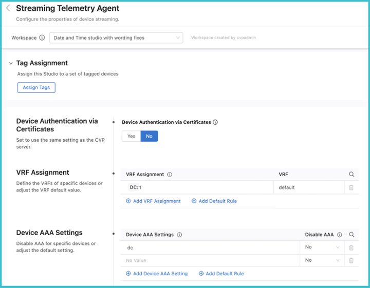
When you open the Studio, the following screen will be displayed.
Authentication
- Certificate
- Ingest key
If you select No, the ingest key will be used, which is a shared cleartext key. This key is defined as part of the CloudVision set up process.
By selecting Yes, certificates are used for streaming authentication. CloudVision generates a JSON Web Token (JWT) that is then saved to a temporary location (e.g. /tmp/token). This token is used by TerminAttr for the initial secure authentication, and once authentication is successful, TerminAttr generates a certificate signing request (CSR) and sends it to the CloudVision server, which then signs the CSR with its own CA certificate and provides the generated client certificate to TerminAttr and stores it in the certificate partition on EOS. After this, TerminAttr will switch to using the client certificate and key, and renames the token by appending .backup to the filename and will not use it anymore.
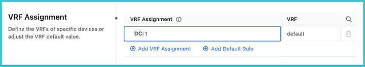
VRF Assignment
Once you have selected the mode for authenticating the data, the VRF assignment can be selected. Here you will select devices with a tag query and then assign them to a VRF.
Device AAA Settings
You can select devices using a tag query and disable elements of AAA for them.
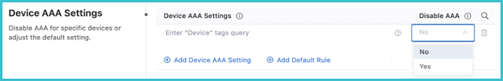
When disabling AAA, you are disabling authorization and accounting for eAPI commands sent by CloudVision to TerminAttr only when the Advanced Login setting is used. This does not affect AAA for other transports, such as SSH or eAPI over HTTPS.
The Advanced Login setting has been the default login method since version 2021.2.0. It can use multi-factor authentication and one-time passcodes to authenticate all CloudVision managed devices when you authenticate with CloudVision. When you select Yes, all eAPI requests are sent over the gRPC session established by TerminAttr instead of eAPI over HTTPS.
Disabling AAA is required in situations when the Advanced login setting is enabled and users are authenticated with certain RADIUS servers, where the server does not support authorization requests that do not have a preceding authentication request.
Streaming to Multiple Clusters
The Streaming Telemetry Agent studio allows you to enable streaming to multiple clusters. In addition, you can configure a number of flags, including OpenConfig streaming. Devices stream state to CloudVision by using a streaming agent, TerminAttr. When a device is onboarded to a cluster, the streaming agent is automatically enabled to stream telemetry data. This studio allows you to further configure the agent and to set up streaming to other clusters.
Streaming to other clusters is limited to telemetry data and will not share configuration in Provisioning between clusters. You can select devices by tags and assign them to a cluster to stream data. There is no limit on the number of clusters a device can stream data to. Before streaming to other clusters, the secure onboarding token from each cluster must be copied to devices.
When you want to create a warm backup cluster with telemetry data, you will enable devices to stream to one or more other clusters.You will also enable it when you want to make device telemetry data available to other users of a cluster.
You have the ability to define which devices stream data to another cluster using tags, which will enable only a selection of devices in this cluster to stream data to another cluster. Before enabling multiple cluster streaming, you must copy the secure onboarding token from the other clusters and paste onto the affected devices. This token can be found in Onboard with Certificates under Device Onboarding.
- From the Provisioining tab, navigate toStudios and select Streaming Telemetry Agent.
- Enable Multiple Clusters.
Figure 18. Enable Multiple Clusters /Enable%20Multiple%20Clusters.png)
- Create a cluster profile.
Figure 19. Create a cluster profile /Create%20a%20cluster%20profile.png) A cluster profile provides the connectivity configuration for another cluster. You'll assign a cluster profile to sets of devices to enable those devices to stream data to that cluster.
A cluster profile provides the connectivity configuration for another cluster. You'll assign a cluster profile to sets of devices to enable those devices to stream data to that cluster.- Cluster Name: The cluster name does not need to match the configured name of the cluster. You can enter any value.
- Ingest Port: The cluster interface that receives telemetry data. This can be either 9910 for on-prem CVP or 443 for the cloud service.
- CV Addresses: Click View and configure the IP addresses of the cluster nodes.If the cluster is a single node only, you can just configure the first node address.
- Add a set of devices that you want to stream to another cluster.
Figure 20. Add a set of devices to stream /Add%20Devices%20to%20Stream.png)
Devices are identified with tags. If you want to provide a back-up cluster with all streaming data, use the device:* or create and use a tag that identifies a group of devices.
Note: If devices have a different management VRF or use different source interfaces to connect to CloudVision, you should only select tagged devices that share a common VRF and source interface. - Select a set of devices in Device Configuration and assign a cluster profile.
Figure 21. Assign a cluster profile /Assign%20Cluster%20Profile.png)
Assigning a cluster profile identifies the cluster that devices will stream state to.There is no limit to the number of clusters a device can stream to.
- Select the cluster profile to configure further properties.
- VRF Assignment: If the device is on a VRF, enter the VRF name. If devices are on multiple VRFs, you will need to delete this set of devices and select a tag for devices only on a single VRF.
- Auth Type: You must select token (for on-prem) or token-secure (for CVaaS)
- Onboarding Token Location: Select the file path where you saved the onboarding token for the cluster devices will stream to
- Source Interface: Enter the name of the interface used to connect to CloudVision. The name should match the device running config, e.g. VLAN 600, Loopback100
- Proxy Address: If devices need to communicate with the cluster through a proxy address, enter an address in the advised format (e.g. http://username:password@192.0.2.1:3128)
When the workspace is submitted and the associated change control executed, the devices will begin streaming to multiple clusters.
Custom Flags
Custom Flags allows you to assign streaming agent configuration to sets of devices. This allows you to assign proxy addressing, ECO DHCP collection, the streaming agent interface, OpenConfig streaming, and other configurations.
Configuration is assigned to sets of devices using tags. The device:* tag will assign configuration to all devices in this cluster. If devices are on different VRFs or the streaming agent used different interfaces, you should use or create and use a tag that identifies a subset of devices sharing these properties.
- Enter a tag to identify a set of devices to configure.
Figure 22. Create a custom tag /Create%20a%20tag.png)
- Select a tagged set of devices.You will be able to configure the following properties for the devices:
- Dynamic Device Configuration: If devices are in dynamic MSS-G segments, you should enable this setting.
- OpenConfig Streaming: The management API GNMI must be configured on devices. This setting is needed for devices on EOS GNMI servers.
- Proxy Address: If devices need to communicate with the cluster through a proxy address, enter an address in the advised format (e.g. http://username:password@192.0.2.1:3128)
- Source Interface: Enter the name of the interface used to connect to CloudVision. The name should match the device running config, e.g. VLAN 600, Loopback100
- ECO DHCP Collector: As of TerminAttr v.1.6.0, the ECO DHCP Collector is enabled by default and listens on 127.0.0.1:67 for UDP traffic. Add 127.0.0.1 as an IP helper address on VLANs to capture device identification.
Submitting the workspace and executing the associated change control will push this configuration to devices.
Campus Fabric
The Campus Fabric Studio provides a single point of control over the configuration of a campus network. The Studio is designed to allow the user to deploy and manage campus devices within the network using design patterns consistent with Arista best practices.
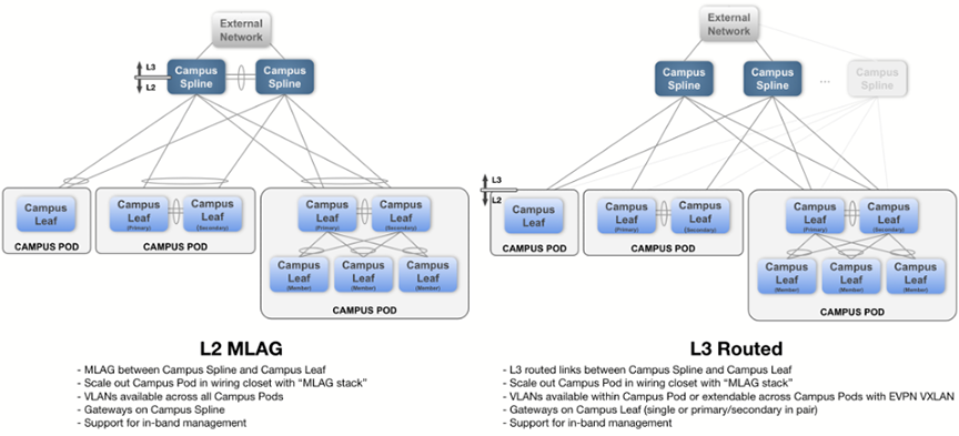
The Studio supports two common campus fabric designs. These designs are illustrated below, with support in beta-version for the L2 MLAG fabric.
For more information, refer to Deploying and Configuring a Campus.
Deploying and Configuring a Campus
Select Campus Fabric to display the Campus Fabric screen.
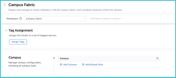
To create a new campus, click Add Campus and enter a name for the campus network. When done, click the arrow on the right.
The main configuration screen for the campus will be displayed.
To assign devices that belong to this campus,cick the dropdown arrow beside Tag Assignment and click Assign Tags. You can now add devices with a tag query to this campus network. If a desired device is not present, add it using the Inventory and Topology Studio or, if the tag is not present, create a new User Tag.
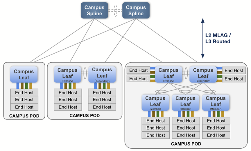
Next, configure the parameters and aspects of the L2 MLAG fabric. These parameters are used throughout the campus network when an MLAG pair exists. Configure the VLANs that will be defined for the campus network. A special management network may be defined when in-band management of the switches is required. The SVI virtual address is used as the anycast gateway across the campus Spline switches, as well as an IP helper address for DHCP relay functionality.
Central to the configuration of a campus network is assigning the roles to the selected devices in its fabric. They can be either campus Spline devices or leaf devices within a pod.
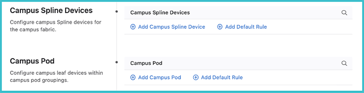
A campus Spline device may be used for both connecting downstream campus leaf switches, as well as connecting hosts. The campus Spline device will often have links toward networks external to the campus fabric.
A pod is a collection of leaf devices that connect to a campus Spline pair of switches. Each pod consists of one or more switches and may be used to form an MLAG stack. Some examples of campus pods are shown below:
The selection of devices available to assign either as campus Splines or as members of a pod are those that you defined earlier on this screen as belonging to the campus.
The connections between devices are configured in the Inventory and Topology Studio. If the devices are already wired-up in your network, they will be shown there. If not, the intended connections can be specified in that Studio, and configuration for those interfaces will be generated.
- Between campus Splines: all interfaces connecting to the two Splines will be configured as an MLAG peer-link port channel.
- Between Splines and campus pod primary and secondary: these connections are referred to as “uplinks” and “downlinks”. They should be arranged according to the L2 MLAG design shown above. Configure these connections as multi-chassis link aggregation (MLAG) port channels.
- Between the campus pod primary and secondary: all interfaces of the two leaf switches will be configured as an MLAG peer link port channel.
- Between pod primary and secondary and pod members: the connections between these devices are configured as multi-chassis link aggregation (MLAG) port channels
Once the configurations of your campus fabric have been set, submit the Workspace and your campus network will be available for review and approval in Change Control.
Layer 3 Leaf-Spine
You’ll use this Studio along with EVPN Services to build a layer 3 leaf-spine network. The L3 Leaf-Spine Studio configures Day 1 deployment of the network, and EVPN Services configures Day 2 operations.
The Studio has been designed to support the following Arista validated L3 leaf-spine design:
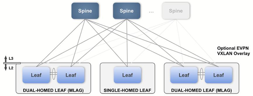
Layer 3 Leaf-Spine - Required Tags
The following device tags must be in place before configuring the inputs in this Studio. You can create these tags within the same Workspace by accessing Tags.
| Tag | Example | Description |
|---|---|---|
| DC | DC: DC1 | DC defines the data center that is being configured. |
| DC-Pod | DC-Pod: DC1 | Data center pod name. |
| Role |
Role: Leaf Role: Spine |
Device Role. Can either be a leaf or spine. |
| Spine-Number | Spine-Number: 1 |
The number for a spine device.Each spine must have a unique number. |
| Leaf-Domain | Leaf-Domain: 1 |
Specifies the leafs within a common AS, which is usually an MLAG pair of leafs.The value must be an integer. |
| Leaf-Number | Leaf-Number: 1 |
The number for a leaf device.Each leaf must have a unique number. Leaf pairs are assumed to be numbered consecutively starting with an odd number (e.g. the device tagged Leaf-Number:9 and the device tagged Leaf-Number:10 are two devices in an MLAG pair of leafs). If a leaf is not part of an MLAG pair, just use one number of the odd-even pair and do not use the other number for another leaf (e.g. the device tagged Leaf-Number:1 will be configured as a standalone leaf if no other device is tagged Leaf-Number:2). |
The tag placement is illustrated in the following diagram:

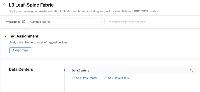
Configuring the Fabric
Once tags are in place, you can create a data center in the Studio using the Data Center (DC) tag.
After a data center is in place, then create and configure its pods. Each pod is a leaf-spine module inside the data center fabric. Use the DC-Pod tag to assign devices to a pod.
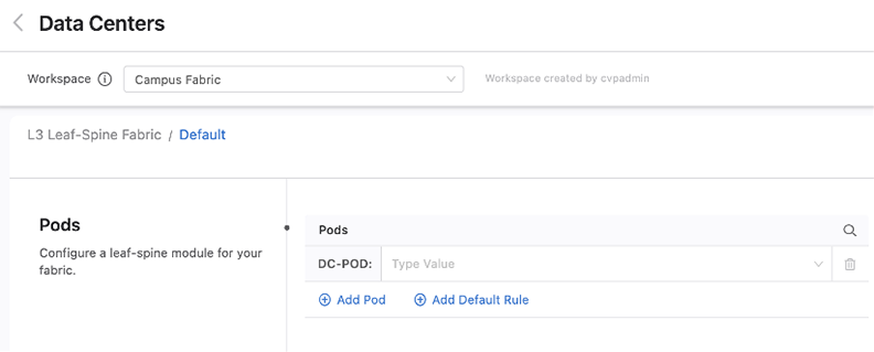
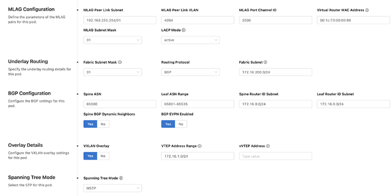
Next,you will be presented with pre-filled values for the fabric of this pod, along with sections that allow you to add leaf and spine devices. Change the fabric configuration for the pod as needed.
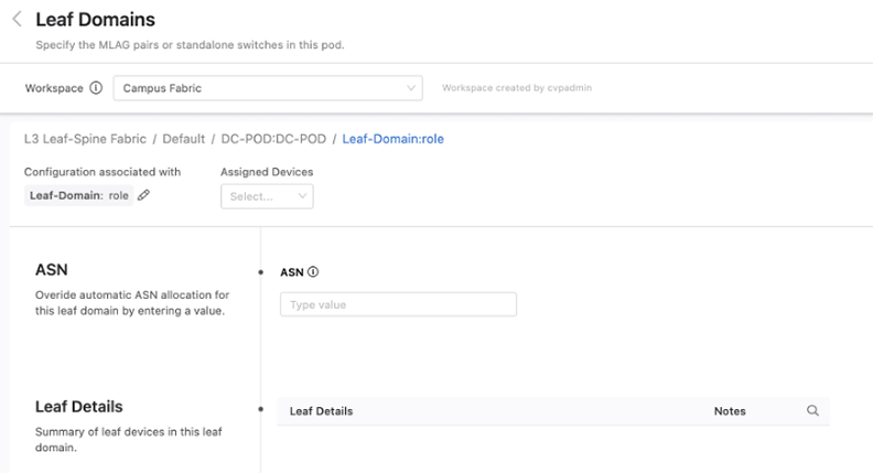
You can add spine and leaf devices by using the Role tag. When adding a leaf device, you can further specify an ASN that will override the ASN number set at the pod level. You’ll also be able to see on this screen a summary of all the devices in this domain.
Once you have configured all the data centers, pods, and their devices, review and submit the Workspace. A change control containing the configuration updates associated with the changes from the Workspace will be created. Review, approve, and execute the change control for the fabric configuration defined in the Workspace to take effect in the network.
EVPN Services
The EVPN Services Studio allows you to deploy L2 and L3 network services. These services are applied to tenants that you create. Each tenant shares a common Virtual Network Identifier (VNI) range for MAC-VRF assignment.
EVPN Services - Required Tags
The following tags are required for this Studio. They will already be in place if you have deployed an L3 leaf-spine fabric with the Layer 3 Leaf-Spine Fabric Studio.
| Tag | Example | Description |
|---|---|---|
| router_bgp.as | router_bgp.as:65050 | Defines the BGP ASN that the switch will use when configuring overlay VRFs, VLANs, and VLAN aware bundles. |
| router_bgp.router_id | router_bgp.router_id:172.16.0.1 | Defines the BGP Router ID used on the switch and makes up part of the route-distinguisher and route-target fields. |
| mlag_configuration.peer_link | mlag_configuration.peer_link:Port-Channel2000 |
Specifies the MLAG peer link used on a switch that has
an MLAG peer.
Note: This tag is only necessary for MLAG peer
relevant configuration. |
| Leaf-Domain | Leaf-Domain:1 | Specifies the leafs within a common AS, which are usually an MLAG
pair of Leafs. The value must be an integer. Note: This tag is only necessary for MLAG peer relevant
configuration.
|
| Leaf-Number | Leaf-Number:1 |
For a leaf device, its number. Each leaf must have a unique number. Leaf pairs are assumed to be numbered consecutively starting with an odd number (e.g. the device tagged Leaf-Number:9 and the device tagged Leaf-Number:10 are two devices in an MLAG pair of leafs). If a leaf is not part of an MLAG pair, just use one number of the odd-even pair and don’t use the other number for another leaf (e.g. the device tagged Leaf-Number:1 will be configured as a standalone leaf if no other device is tagged Leaf-Number:2). Note: This tag is only necessary for MLAG peer relevant
configuration.
|
Configuring EVPN Services
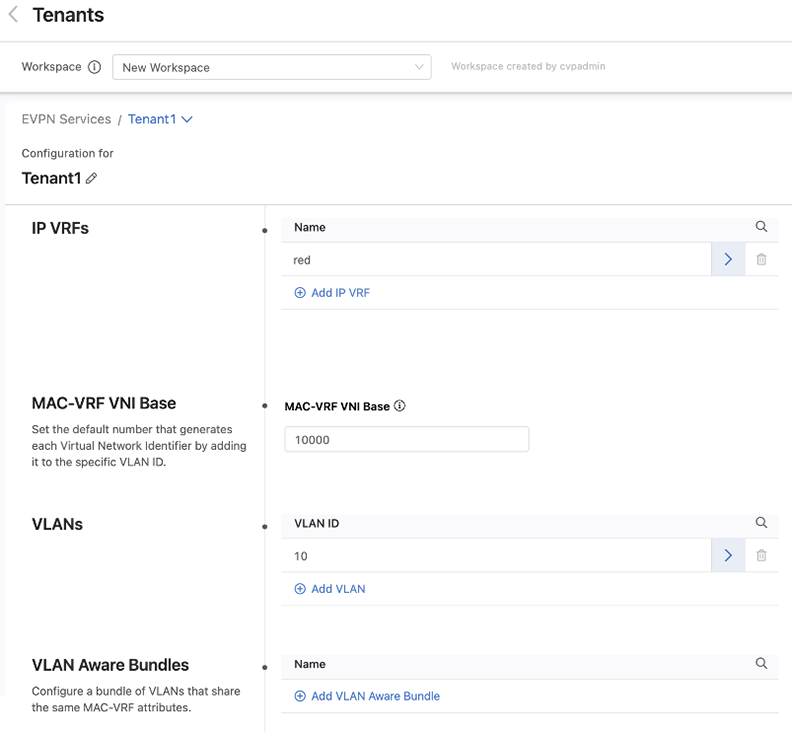
When you open EVPN Services, the following screen will be displayed.From this screen, tenants are created and the default VRF and MAC-VRF attributes for all tenants are created.
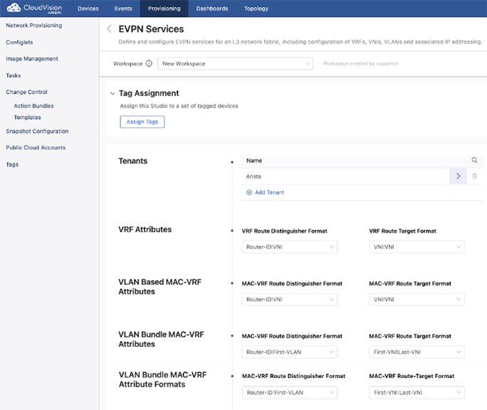
When creating a tenant or selecting an existing tenant to configure, you can create VRFs and VLANs for use within this tenant. You will also determine the base number used to generate VNIs.
VRFs
When configuring a VRF, always specify a VNI. The remaining fields are all optional and their use depends upon how you are configuring your network.
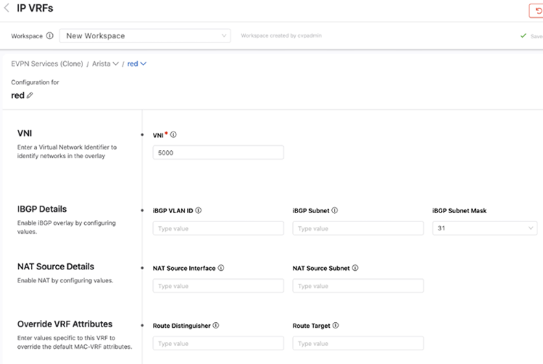
The iBGP Detail fields are necessary when a VTEP is composed of a pair of leaf switches that have a host (or hosts) connected to only one switch in an MLAG pair. If incoming traffic arrives at the leaf switch in the pair that the host is not connected to, the leaf switch will drop that packet. By configuring a VLAN and SVI to establish an IBGP peering on for this VRF, both switches in an MLAG pair are aware of all host connections including those connected to only one switch.
NAT Source Details are used to configure a virtual source NAT address for the VRF. It is used mainly for troubleshooting, because all VTEPs share the same IP address and MAC address for each SVI. This means that pings to workloads behind remote VTEPs or local workloads (e.g. MLAG VTEPs) may not be successful because the reply cannot be returned. When the destination host responds to either an ARP request or ICMP echo request, the reply is processed by the first VTEP it arrives at, which is because all VTEPs have the same IP and MAC address. In order for each VTEP to successfully ping a workload, configuring a NAT source address enables a dedicated loopback interface that can be used as the source address for pings within a VRF.
The Override VRF Attributes section allows you to override the default VRF attributes associated with this VRF.
VLANs
A name must be provided for each VLANthat is created.Then select whether it is applied to a routed or bridged setting.
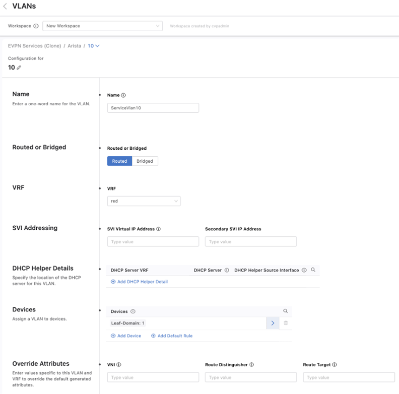
By default, the toggle is set to routed. You can also provide details of a DHCP server and provide a default gateway by entering a Switched Virtual Interface (SVI) virtual IP address, which are options only available with a routed VLAN.
The last two options, Devices and Override Attributes, are shared with a bridged VLAN, where devices can be assigned to this VLAN and override the default values generated for configuration elements associated with this VLAN.
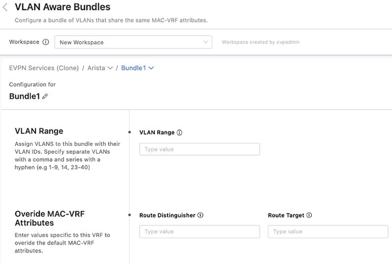
VLAN Aware Bundles
You can bundle VLANs that have already been created within a tenant into VLAN aware bundles. Each bundle consists of a range of VLANs that share the same MAC-VRF attributes, which you can define by overriding the default MAC-VRF attributes shared across tenants.
Segment Security
The Segment Security Studio enables you to separate your network into logical domains. Each domain contains a set of segments and policies that determine the forwarding behavior between segments. A segment describes a set of endpoints with identical security policies and network access privileges.
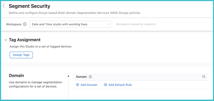
To create a segmentation domain, click Add Domain and enter a device tag query. A segmentation domain is identified by device tags, which gives you the ability to select a group of switches that form the domain. All devices in the same domain will be configured with identical segmentation policies.
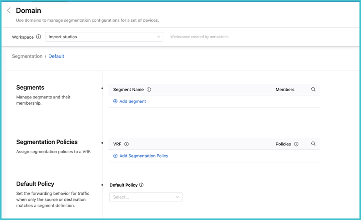
Once you have created the domain, click the arrow on the right, and the Policies screen will be displayed.
Enter a segment a name and identify its members. The segment membership is based upon either IPv4 or IPv6 prefixes, or both.
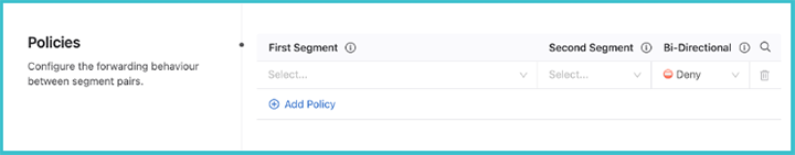
Next, set the security policies between segments. These policies apply to a single VRF. Configure segment policies for the VRF by clicking View underneath the Policies heading. Determine the relationship between pairs of segments inside the domain and the forwarding behavior of traffic between them.